
The "Simpleboost" Kit for Thinkpads
for the X60, X60s, X60t, X61t, X61s, and X61t in particular
| simpleboost | notes | dim range | ~cost |
|---|---|---|---|
| PWM-mode mod |
boost, 30-50V output, 10 LED strings minimum for 20V input |
6:1 | $15-20 |

|
|||
|
|||
This driver is a simple boost convertor with constant-current output. Some vendors sell it with an additional flat-ribbon connector, most sell it with the ribbon connector missing and those solder pads left bare as in the pic above. The identifcation marks on the controller IC are usually ground off; I don't know why some Chinese vendors do this. The IC is the DF6113 boost controller popular in many LED drivers, and this board's design is straight off of the DF6113's datasheet.

Above: Schematic of stock, unmodified "Simpleboost" LED driver board
The LEDs provided with the kit must be arranged in at least 10S strings for Thinkpads with internal 20V power (like the X60/61-series) else the LEDs will never go out completely even when the machine is 'off'. It seems these 12.1"/255mm kits usually come with 60 LEDs in 10S/6P; that works fine.
This controller board requires modification (such as the one below) for use with a Thinkpad.
The PWM mod alters the driver board slightly to use the Thinkpad's PWM brightness signal as a direct backlight switching control. The PWM frequency is 200Hz unless the OS changes it. If backlight flicker bothers you, definitely use one of my continuous-mode driver boards instead.
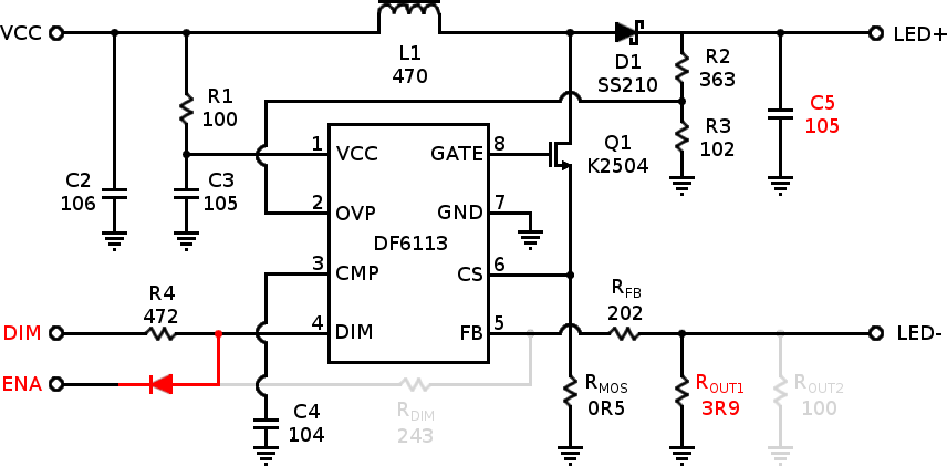
Above: Schematic of the Simpleboost driver board modified for PWM-mode operation with a Thinkpad. Red marks new or altered components and connections, light gray shows removed connections and components.
Specific package recommendations above are known to fit, but feel free to use either surface mount or through-hole components as convenient. Resistor values should be 1% tolerance for best results.
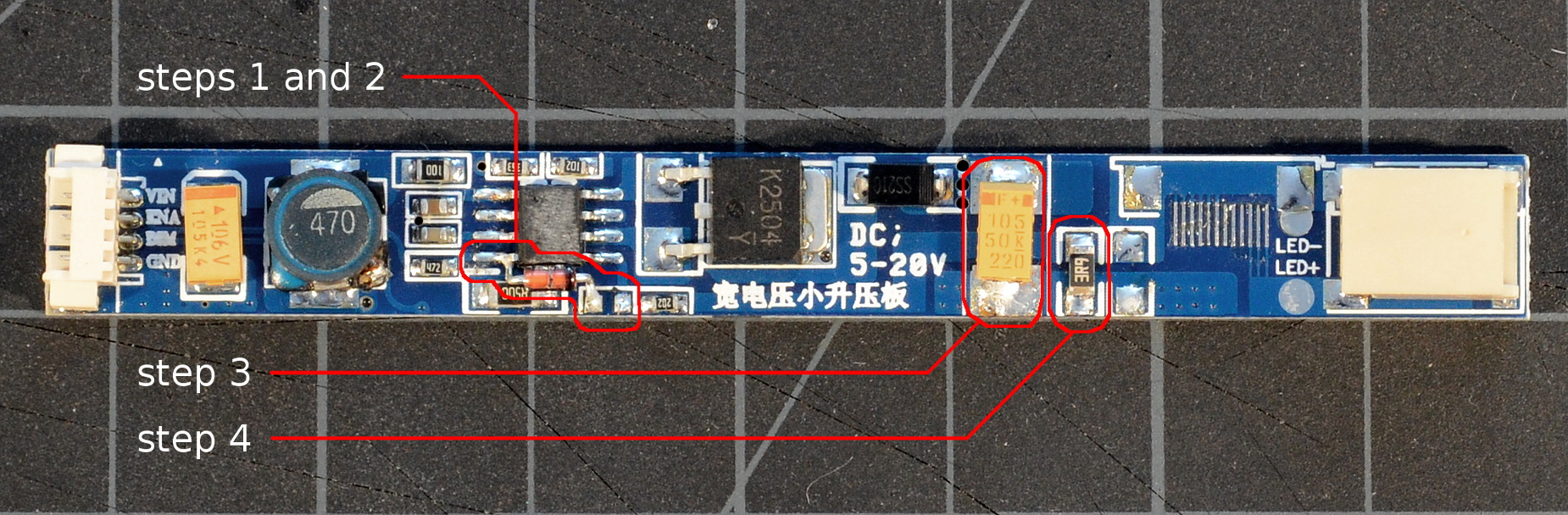
Above: Simpleboost driver board after PWM-mode mod. Changes from stock are circled in red. Click for a larger image.
After modding, the DIM input is now the board enable and the ENA input is now a PWM-compatible brightness input (they're mostly interchangeable really, but reversing them will alter the output current drive slightly.
If there's no space to stash the LED driver PCB somewhere in the lid (or if you simply find adding the extra board inelegant), the driver PCB can be trimmed down to fit directly onto a stock Thinkpad inverter board. We only need to relocate the current sense resistor from the right to the left side of the output capacitor.
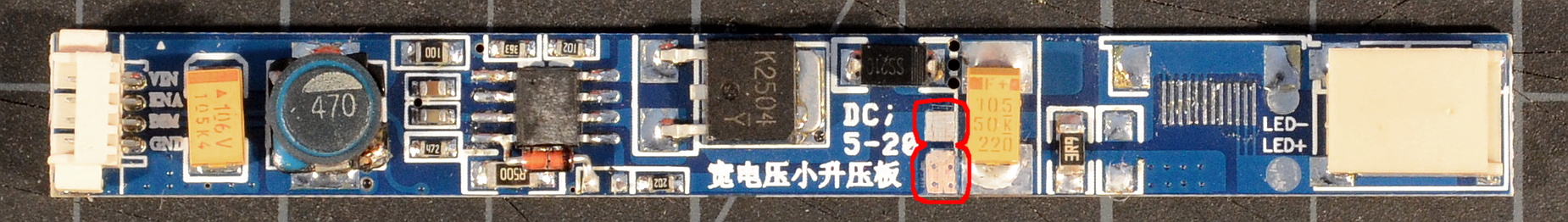
Above: Trimming the Simpleboost driver board requires relocating the current sense resistor; expose the circled trace areas to make new pads for the resistor. Click for a larger image.
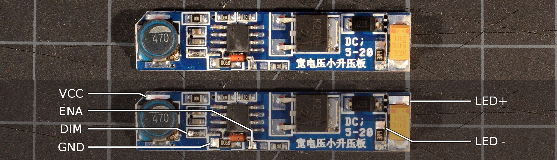
Above: Trimmed LED driver board with completed PWM mod intended to be soldered onto a Thinkpad inverter. Mouse over the image to highlight and label the connection points.
Note that we've cut the power supply decoupling capacitor off along with the input connector. We don't need it in this case; the DF6113 is a fairly stable controller and we'll use a decoupling capacitor as our power tap when we graft the driver onto an inverter board.