
Connecting LED Backlights to Thinkpads
for the X60, X60s, X60t, X61t, X61s, and X61t in particular
If you've modded a general-purpose LED driver for use in a ThinkPad, you'll need to find space for it in the Thinkpad lid and then wire it into the existing power and brightness controls.
Of course, there's virtually no extra room in the lid of an X-series notebook. The tablet models have a bit more space along the bottom of the LCD panel, but it's still cramped. For all of these models, building a small-enough driver and installing it onto the existing inverter board is probably the easiest strategy.
The X40 and X41 models use a number a slightly different versions of [as far as I know] three basic inverter variants. One is specific to the tablet models, and two to the other models. The inverters for a given model are functionally interchangeable.

Above: Front and back views of inverter 39T5655 [Foxconn] for the Thinkpad X40 and X41. Inverter 27K9993 [AMBIT] appears to have an identical layout with slightly different component choices and silkscreen text.
Components to be removed are circled in red. Locations of the power, ENA, and DIM connections are highlighted in blue. Click for a larger image.
Above: Front and back views of inverter 39T5657 for the Thinkpad X40 and X41. Inverter 27K9991 appears to have an identical layout with slightly different component choices.
Components to be removed are circled in red. Locations of the power, ENA, and DIM connections are highlighted in blue. The DIM signal can also be pulled from pin 25 of the inverter connector. Click for a larger image.
Above: Front view of inverter 41W1109 for the Thinkpad X40 and X41 tablet models. Components to be removed are circled in red. Locations of the power, ENA, and DIM connections are highlighted in blue. Click for a larger image.
The six X60 and X61 models use one of (as far as I know) four possible inverter boards. Two are specific to the tablet models, and two to the other models. The inverters for a given model are functionally interchangeable.

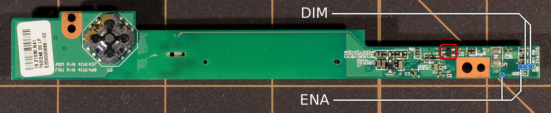
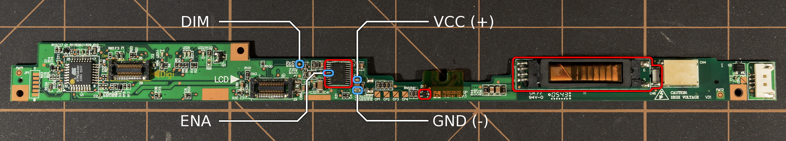
Above: Front and back views of inverter FRU 41W1468 for the Thinkpad X60 and X61 tablets. Components to be removed are circled in red. Locations of the power, ENA, and DIM connections are highlighted in blue. ENA and DIM can be taken either from the small testpoint or from the neighboring resistor's pad. Click for a larger image.

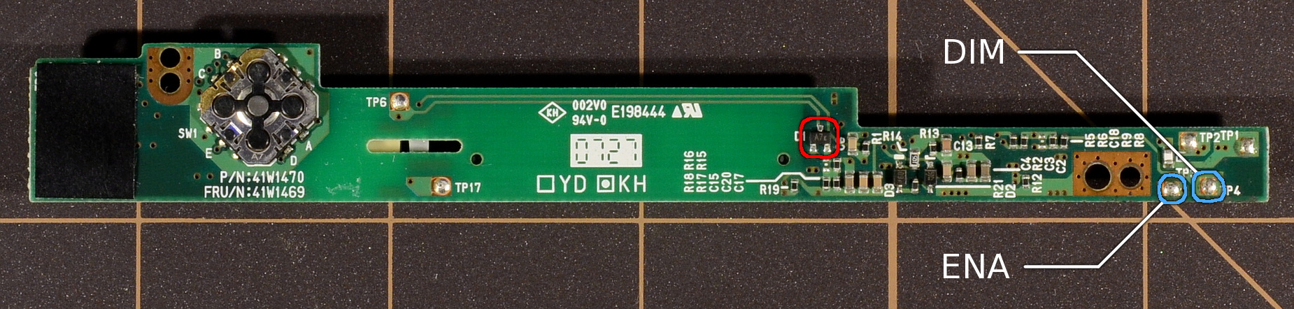
Above: Front and back views of inverter FRU 41W1469 for the Thinkpad X60 and X61 tablets. Components to be removed are circled in red. Locations of the power, ENA, and DIM connections are highlighted in blue. Click for a larger image.
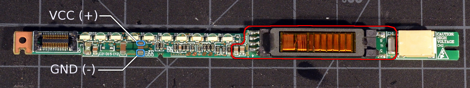

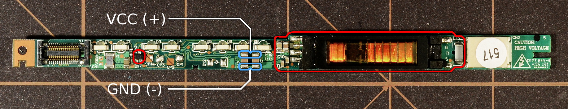
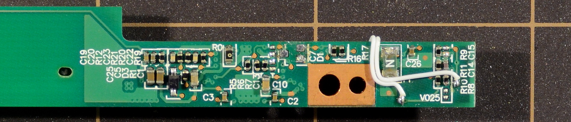
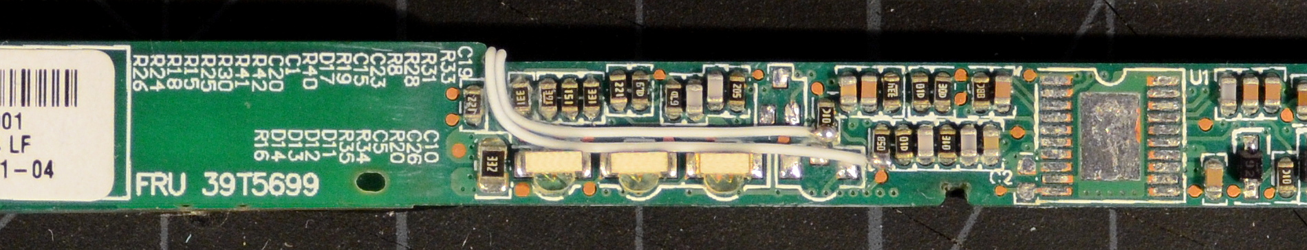
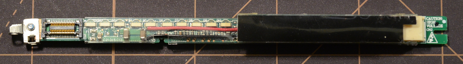
Above: Front and back views of inverter FRU 39T5699 for Thinkpad X60, X60s, X61, and X61s. Components to be removed are circled in red. Locations of the power, ENA, and DIM connections are highlighted in blue. Click for a larger image.
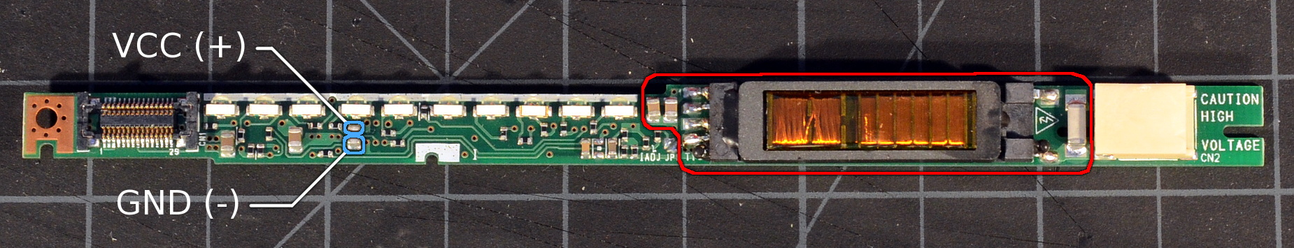
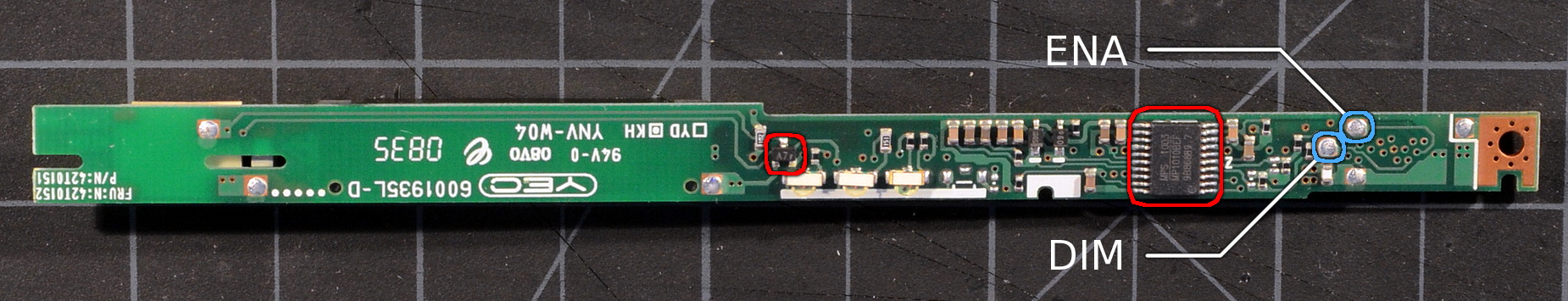
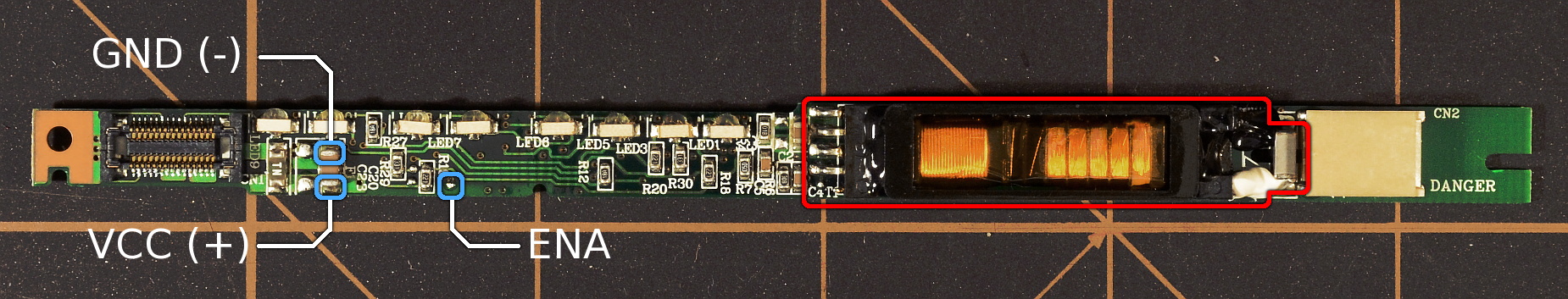
Above: Front and back views of inverter FRU 42T0152 for Thinkpad X60, X60s, X61, and X61s. Components to be removed are circled in red. Locations of the power, ENA, and DIM connections are highlighted in blue. Click for a larger image.
The components that are necessary to remove are the same on all four inverter boards, but located in different places (see pictures above). Remove the step-up coils, coil output capacitor, the three-terminal diode package, and controller IC. The IC can be removed either using a parallel/tweezer soldering tool, or by applying sufficient heat to the IC package. The solder pads for the IC leads are fragile and will lift easily, but if neatness isn't a requirement, destroying the pads won't cause any trouble for our use. Do not leave any shorts from solder bridges between the pads.
A few other components are circled on the front of the boards mainly because they're no longer used and potentially get in the way. Don't simply wipe random components off the inverters; some are needed for the buttons and secondary lid switch on the tablets, or the LEDs on the other models.

Above: Hot air or a parallel removal tool are the easiest ways to neatly remove the controller IC. Alternately just use an iron to apply sufficient heat to the IC package to melt the solder on the leads and underlying pad.
If you're not using one of my ThinkPad LED conversion boards, you'll probably need to trim your driver board to fit in place on the ThinkPad inverter.
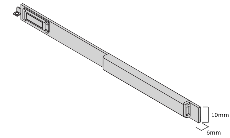
The inverter boards on the tablet models can accomodate an LED controller PCB as large as 46mm (length) by 11.5mm (width) by 5.25mm (height). Clearances in the X6X and X6Xs (and other thinkpad models) are somewhat tighter than on the tablet models. The final inverter board, mounted on-edge, can be no taller than about 10mm else the lid bezel will no longer mate flat. The board can also be no thicker than about 6mm for a clean fit along the inner edge of the lid. Thicker assemblies will fit, but only if we bend the inverter board into place (note that even the stock board is flexed slightly, presumably to keep it wedged into position so it doesn't rattle). If we wish to reuse the slip-on inverter shield (probably a good idea), that restricts the maximum LED driver PCB size further.
All restrictions considered, an LED driver board that fits onto any X6X model's inverter and still be able to slip the original inverter shield back into place shouldn't exceed 46mm (length) by 9.25mm (width) by 4.4mm (thick).
For example, the Simpleboost, Unboosty, and Unboosty-Blue kit driver boards, even built in trimmed form, are all slightly taller than 10mm. That said, they have no delicate traces near the board edges. The top and bottom edges can be cut, filed, or sanded down to bring the board height down as far as 9mm, leaving more than enough room to slip the original 9.5mm tall plastic inverter shield back into place.

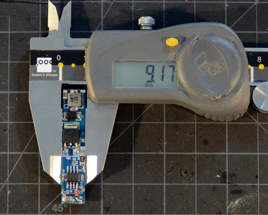

Above: PWM-modded Unboosty-Blue board trimmed and fitted with a low-profile inductor. It's well within the 46mm x 9.25mm x 4.4mm limit to fit easily on any model.
Thickness is potentially a larger problem due to inductor height. The LED backlight kits use different inductor parts from batch to batch; some examples of a given kit will fit as-is, most will not. On non-tablet models, you will probably need to swap the stock inductor for a lower-profile option. Inductors with a 6028 footprint are fairly common and fit nicely.
There's one last bit of board prep that eases later assembly: Undercut the edges of the underside of the board slightly. This helps prevent accidental shorts when soldering the board in place later, especially near the output connector.
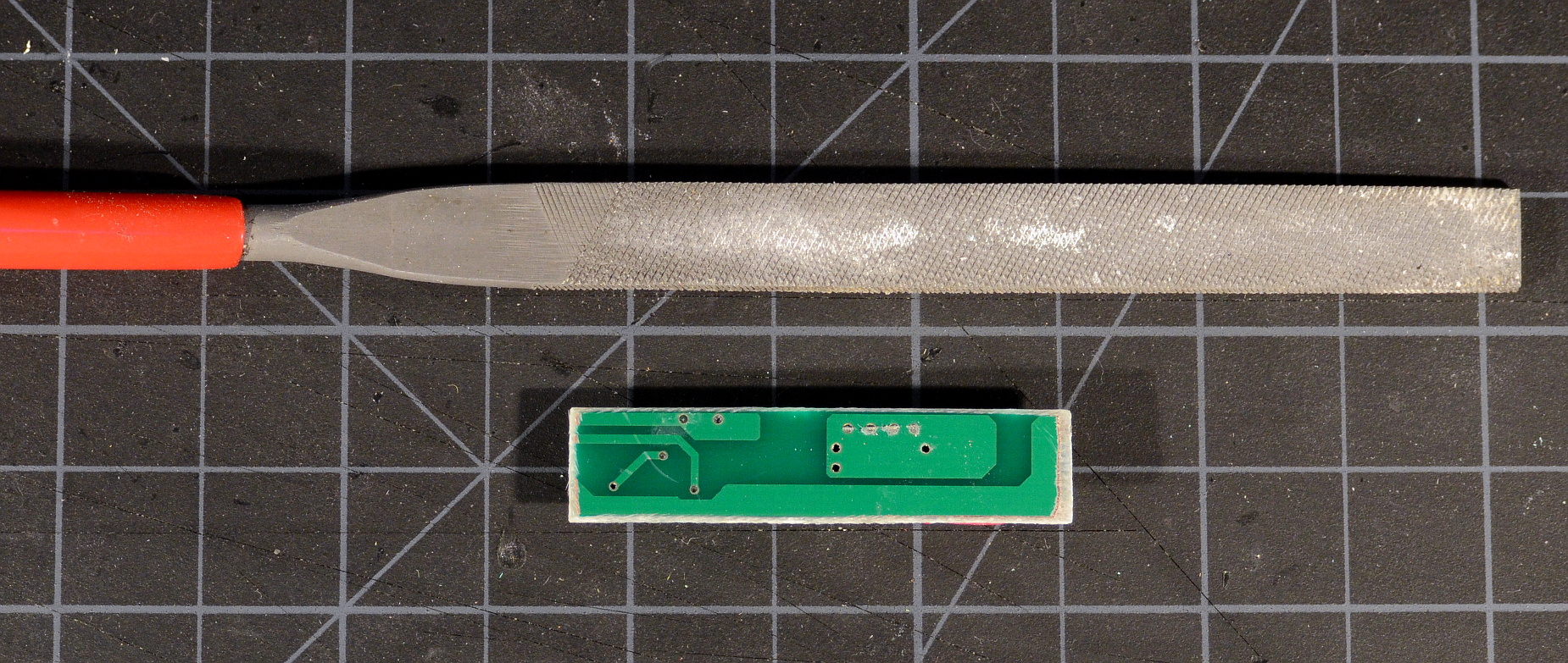
Above: Undercutting the bottom of a trimmed LED driver board before installation moves exposed copper away from the edges, helping prevent any accidental shorts during final assembly.
We attach the trimmed LED driver board to the empty area on the inverter previously occupied by the inverter coil. The easiest option is some adhesive transfer tape (ie, double sticky tape made for permanent industrial assembly). We could also just crazy-glue the board in place, but tape is less messy, reversible, and provides some additional electrical insulation from the exposed solder pads on the underlying board 'just in case'.

Above: The modded and trimmed LED driver will be mounted to the inverter where the coils were previously located. Adhesive transfer tape, eg, Killer Red, will hold the LED board firmly as well as provide some electrical insulation from the exposed solder pads on the underlying board.
Finally, we connect the driver board. Solder bridges ('giant globs of solder') work well enough to connect the LED + and - pads on some drivers to the output connector. The Simpleboost's LED - connection and the Cheapybuck's LED + connection are in the middle of their respective PCBs, and so require wire. Most of the generic kits come with a useless little wire harness; feel free to cut and reuse this wire for connections.
On the input side, VCC and ground can be tapped from a preexisting supply decoupling capacitor on the front of the inverter. ENA and DIM can be pulled from specific points on the back (see the labeled pics at the top of the section and the completed pictures below). This isn't the only way, or even the visually cleanest way to connect things up, but it's simple, straightforward, and works well.

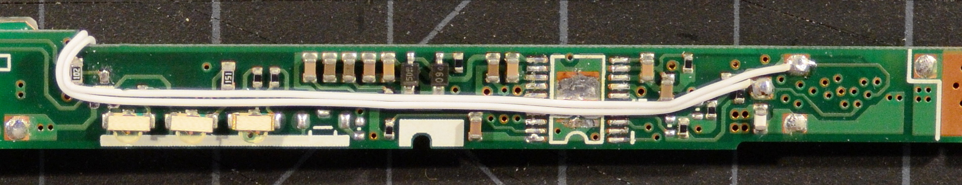
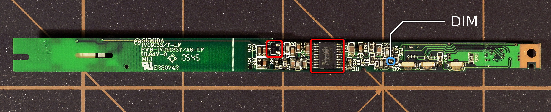
Above: Closeups of the ENA and DIM connections on the back of inverter boards 41W1468 (top), 41W1469 (middle top), 39T5699 (middle bottom), and 42T0152 (bottom). Just in case anyone notices, I accidentally removed an extra capacitor next to the controller IC along with the IC itself on the 39T5699. It has no effect on the modded board.
Once everything is soldered in place, connect the completed inverter onto the LCD cable, plug the LED strip into the inverter and boot the computer to test. Neither the screen nor hard drive need to be connected for the test, that is, a full boot is not required for the backlight to fire and the brightness controls to work.
If the backlight does not fire within a count of ten after pressing the power button, shut the machine off and look for problems. Both the ThinkPad and the LED driver boards are pretty robust, but, eg, an output short can eventually overheat and damage the inductor on the LED driver.
After testing, it's a good idea to use a little CA glue to fix the connections and added components firmly in place. Slip the plastic inverter shield back in place (or wrap in insulating tape) to complete the inverter conversion.
Above: TLD1 driver grafted onto a 39T5699 inverter board (top) and with the mounting bracket and plastic inverter shield replaced (below).