
Installing LED Backlights into Thinkpad LCDs
for the X60, X60s, X60t, X61t, X61s, and X61t in particular
Whatever the LCD panel or LED kit, installing an LED backlight strip into a CCFL-equipped panel follows the same sequence of steps. The instructions below are long and exhaustive, but don't be discouraged; they're just over-detailed for the first-time modder. The high level process is actually pretty simple:
 Opening the lid, Removing the LCD panel
It should go without saying, but remove AC power and the battery before opening the machine. Be aware that the backlight inverter is always powered when the machine itself has powered, even when the machine is turned off.
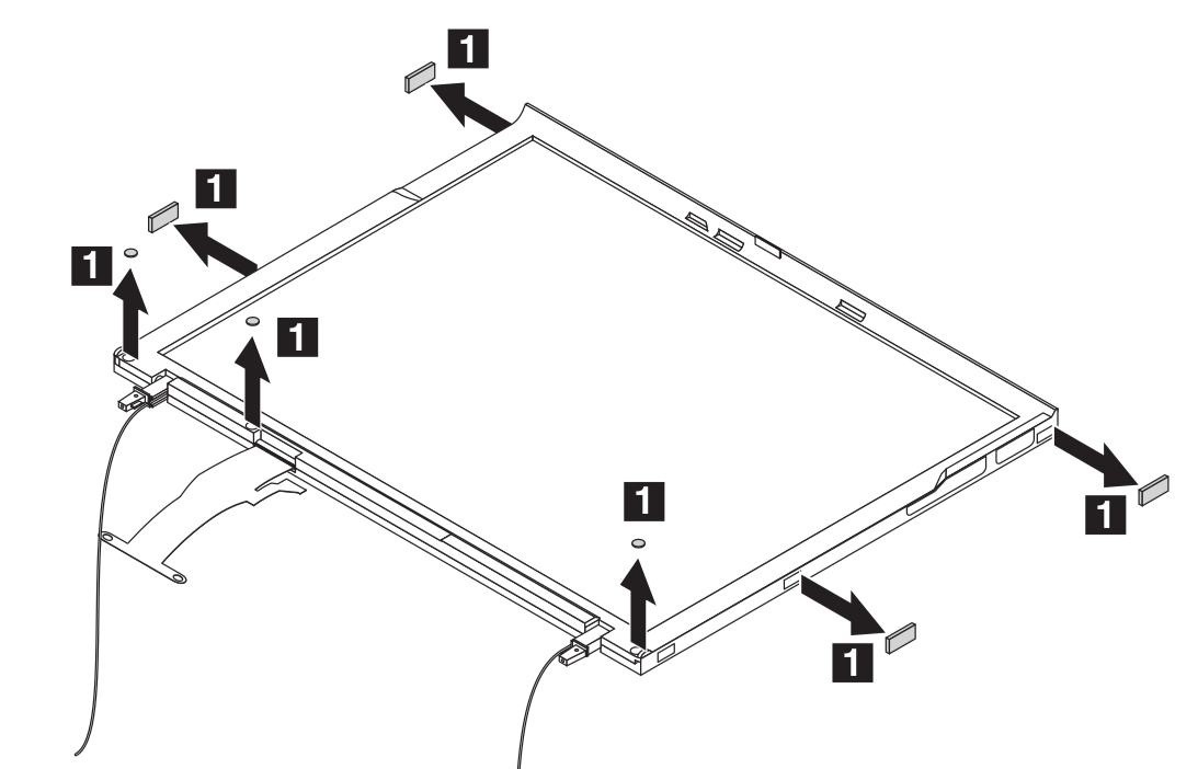
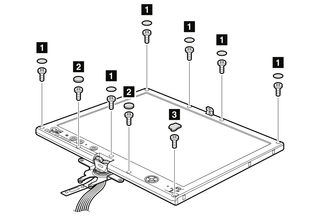
The official Hardware Maintenance Manuals describe and illustrate the lid disassembly process in detail:
Note that it's not strictly necessary to remove the entire lid and hinges from the rest of the laptop, though the HMM recommends this.
The screen bezel is held in place both with screws and small plastic latches along all four sides of the screen; some of the latches pop apart upwards, but most pop apart sideways, often alternating inward and outward. There's some trick to getting them to pop free; a beginner should mostly be aware they come apart fairly easily when pulling/torquing in the right direction. If the plastic is in danger of bending or cracking, that's pulling too hard; back off and try a different direction.
Also, most ThinkPad models have a strip of strong adhesive tape along the bottom edge of the screen bezel, holding the bezel to the bottom of the screen. It will peel free with slow, steady pressure and (although the hardware manual says otherwise), it can be reused a few times. If it's badly damaged or destroyed during disassembly, Killer's 'Red' adhesive transfer tape is a good replacement (really, Killer Red is a staple of laptop modding; if you don't have any, get some and you'll wonder how you lived without it).
As per the HMM, unplug the LCD screen from both the inverter board and LVDS cable and set it aside for now. Also unplug and remove CCFL inverter board.
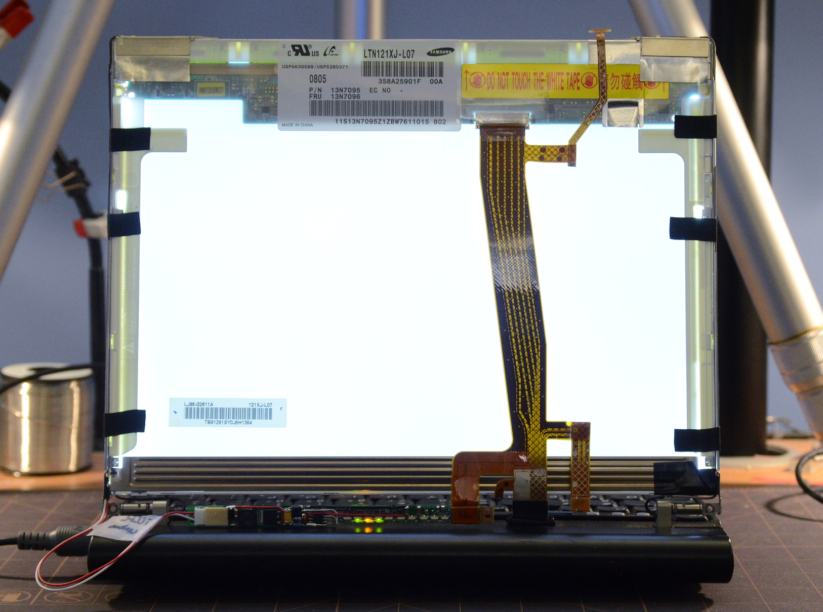
Testing the backlight now ensures it arrived in working condition, which can narrow down the troubleshooting possibilities if a problem occurs later during installation.
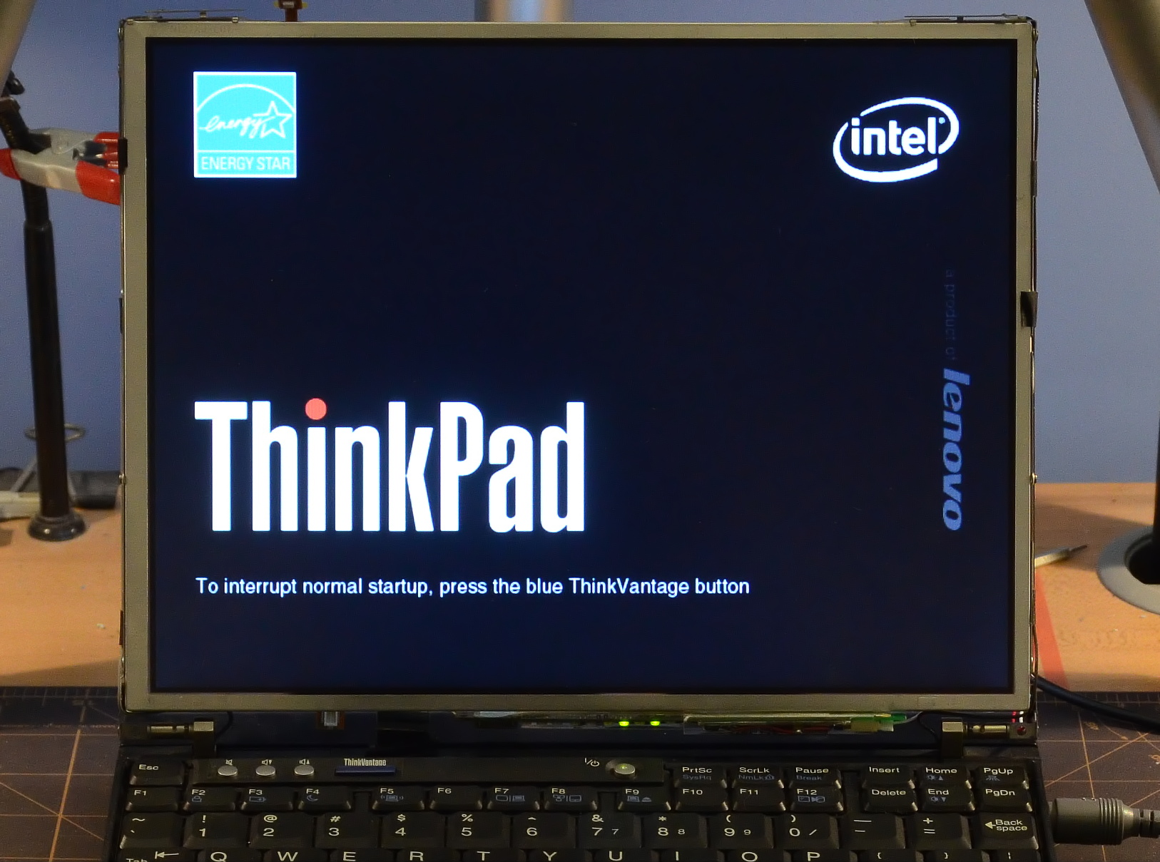
Plug the LED strip into the LED driver board, and the LED driver board into the LVDS cable. Remove the hard drive, then power the machine on. The laptop will happily boot to the splash screen without an LCD plugged in, not that you can see it.
Within a count of 10, the LED backlight should fire. In this state, the screen brightness controls should work across their full range. If the backlight does not come on, or the brightness controls do not work as expected, promptly shut the machine off and look for connection problems*. Do not leave the machine powered if there is any problem with operation of the backlight.
When working normally, the driver will get warm to the touch, especially at full brightness. The LED strip can get quite hot-- this is normal. Once it's mounted in the panel, it will be able to dissipate heat more efficiently into the metal backlight bracket than it can into free air.
*Note: If an LED driver board that is trimmed for a specific ThinkPad model is plugged into a different model, it's expected that the brightness range may not be entirely correct. There is no danger to continuing to operate the LED backlight.
Now that we know for sure the LED backlight works properly, we can prep for installation.
Clean any crud or debris away from the seams between the LCD's outer metal frame and the rest of the panel assembly. On non-tablet screens, pay special attention to the edges around the front of the panel. Any hard grit that makes its way into the panel will eventually cause the dreaded 'white spots': fuzzy bright points in the panel caused by scratches on the internal acrylic waveguide that's responsible for evenly distributing the backlight illumination. (Tablets are less prone to these spots as the front surface of the panel is sealed.)
The backlight reflector bracket (that houses the CCFL) is normally grounded to prevent stray electric fields from disturbing the CCFL's arc, and to contain any electrical noise generated by the backlight.
Neither is relevant to LEDs, and a grounded bracket poses a short-circuit risk to the LED strip. The inner surface of the bracket is electrically insulated by a plastic film, but the metal edges of the bracket are exposed. LED current flow shorted to ground is not limited/regulated by the LED controller and will blow a fuse either on the inverter (there's only one, near the connector) or on the motherboard itself (fuse F2 on the top of the motherboard near the processor support bracket).
When the bracket is not grounded, the LED strip can only short to itself, which is relatively harmless due to current limiting.
The ungrounding process is covered below, along with disassembly.
Removing the CCFL tube does not require complete panel disassembly, but it does require popping the panel frame slightly open. The LCD panels used in Thinkpads (and most laptops) are held together by a combination of screws, snap-fit hasps, and adhesive polyester tape. Freeing the metal outer/front portion of the frame from the plastic inner frame varies slightly by panel. Look for your panel from the sections below.
The various BOE Hydis AFFS screen options have nearly identical construction. The prep process is the same regardless the specific model number.
If this screen is a finger-touch model (what Lenovo used to call 'multitouch' before that term came to be used for multiple-finger touch sensing), disconnect the ribbon cable stretching from the front of the panel around the side to the Wacom digitizer on the back. The ribbon is often secured to the connector with a dot of polyester tape that's hard to see, and to the Wacom backplane itself with a square of adhesive.
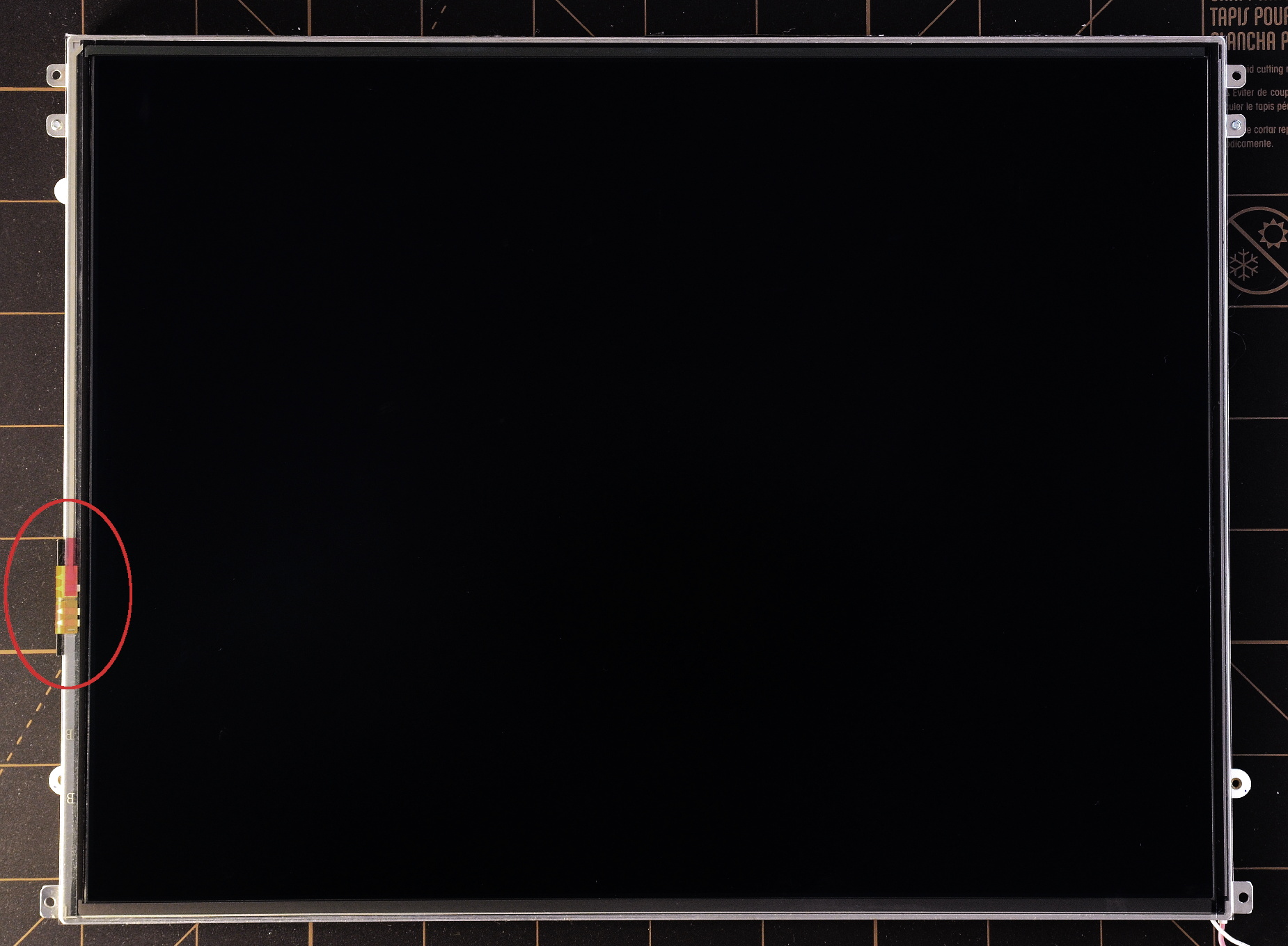
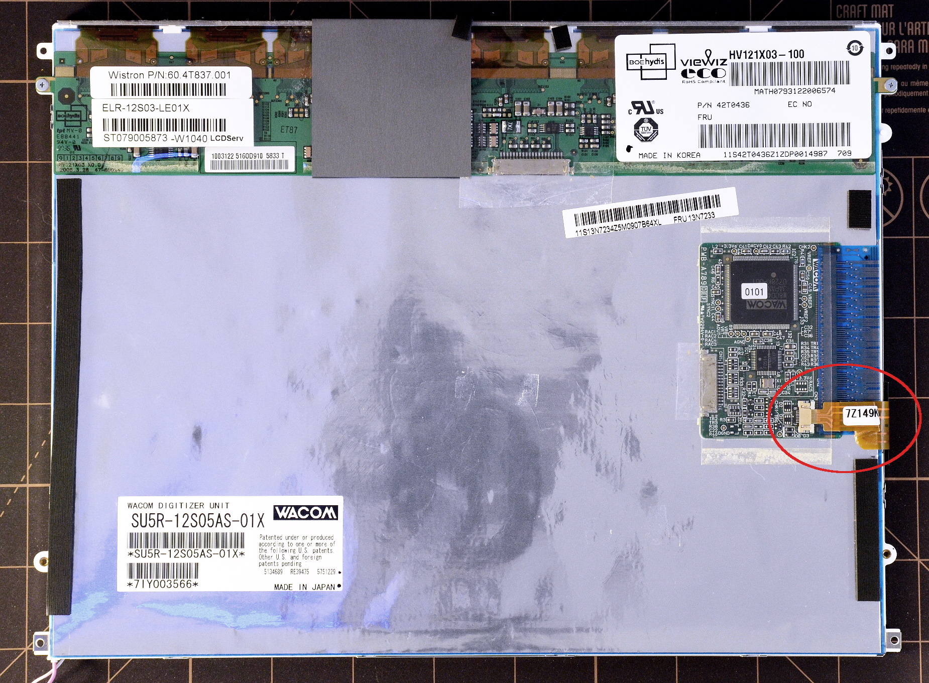
Above: This tablet screen is equipped with a pressure-sensitive front surface to detect finger contact as well as pen-input. The touch sensitive front layer is connected to the Wacom controller via the ribbon cable (circled in red). Finger-touch was available with both the older green-and-rust-colored Wacom backplanes as well as the later blue-and-silver version (pictured). Panels without the indicated ribbon cable accepted pen input only.
Remove the two machine screws fastening the LCD controller board to the frame. BE AWARE: The flexible plastic cables attaching the controller board to the glass LCD are strong; the heat-bonded connections to the board and LCD glass are not. Flexing the cables is mostly safe, but never tug or peel the connection, or try to lift or move the panel by the controller board. If any of those connections pulls free, it's Game Over: the LCD is dead. I don't yet know of any DIY fix.
For what it's worth, I've damaged exactly one of these connections in a decade of disassembling LCD panels. About nine years ago, I fumbled a panel while flipping it over and, without thinking, grabbed at the controller board rather than letting the panel drop onto the soft, cushioned work surface I'd set up to prevent exactly that kind of accident.
On models with a Wacom digitizer backplane that's a thin PCB (the rust/green colored version), also remove the two machine screws securing the backplane. The flexible silver/blue version of the backplane does not have these machine screws.
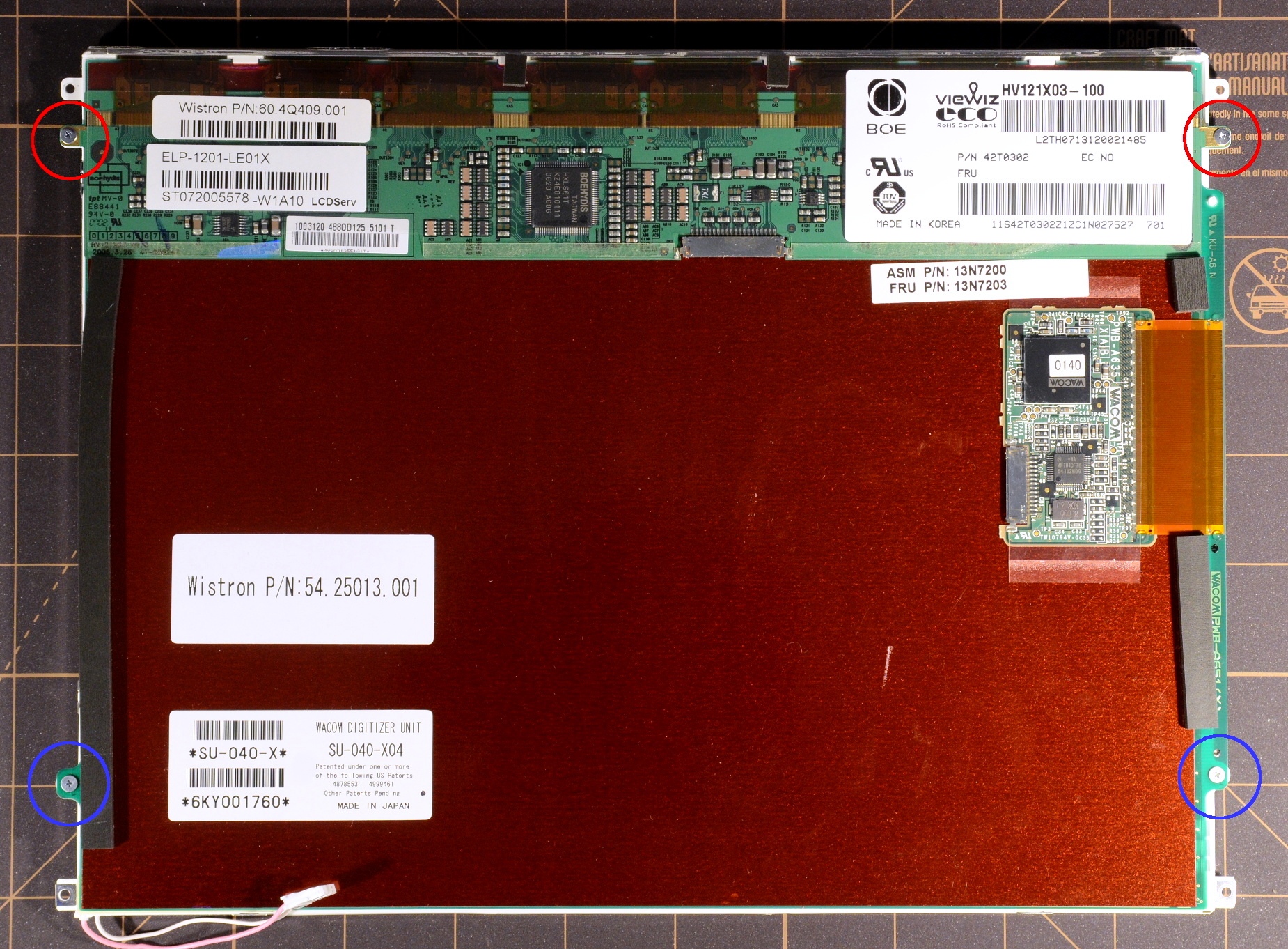
Above: AFFS tablet screen equipped with the older rust-and-green Wacom backplane. This style of Wacom is secured to the screen frame with both tape and two machine screws (circled in blue), where the blue-and-silver version is only taped in place. The machine screws holding the LCD panel controller to the frame are circled in red. This particular screen does not have the finger-touch option.
Carefully remove the Wacom digitizer backplane from the panel. Both versions are secured with double sided tape, one strip along the bottom near the backlight and/or strips up either side of the panel. Pull gently and slowly; do not crease or break the white frame or exposed portions of the white plastic sheet inside the frame. The Wacom backplane itself is fairly sturdy.
Replace (for now) the two machine screws fastening the LCD controller board to the frame. We don't want the controller PCB flopping around during other work. The screws will have to come back out again later to allow replacing the Wacom backplane during reassembly.
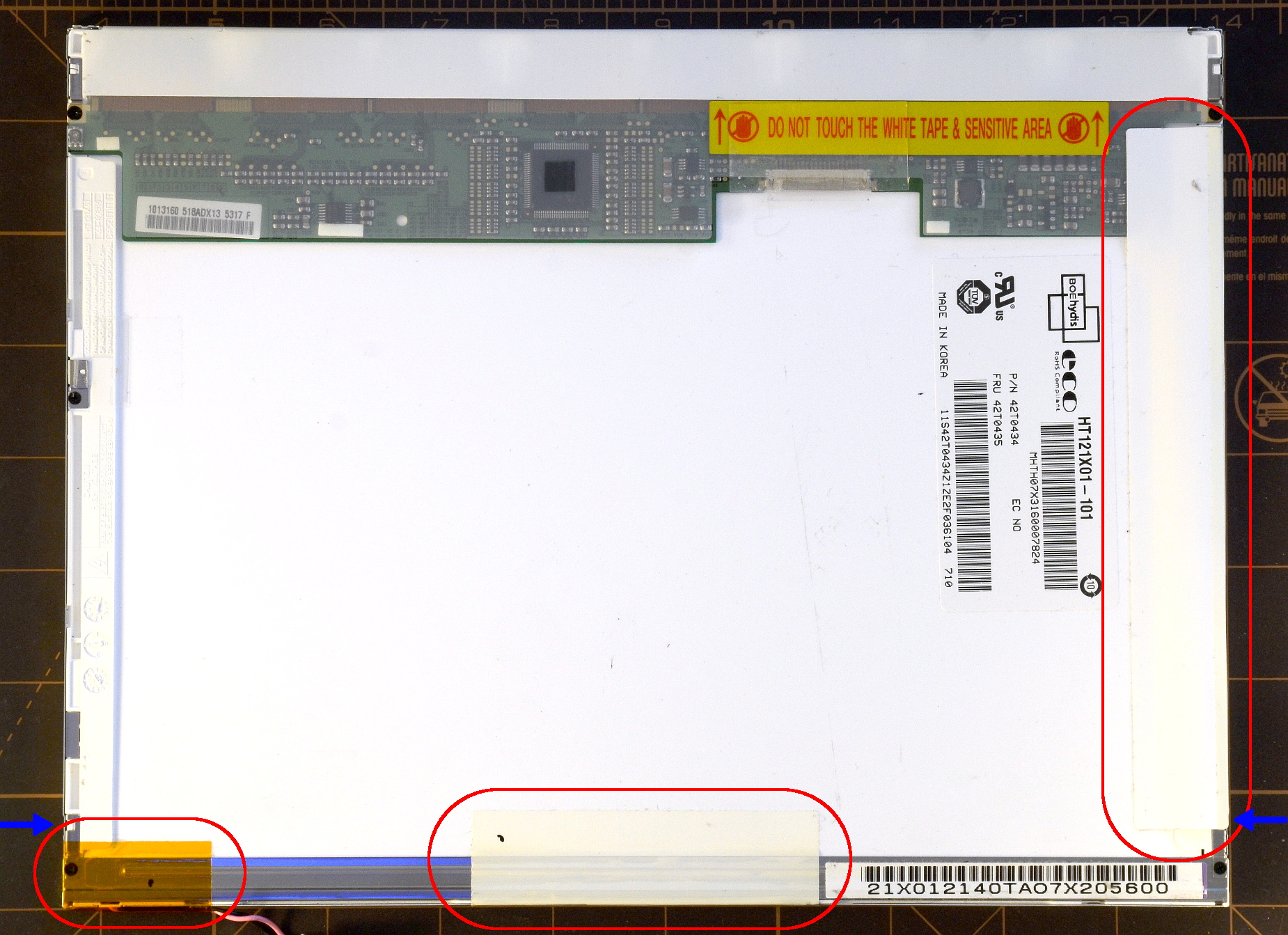
Remove the thin white polyester tape that joins the metal frame to the white plastic frame, located along the bottom of the panel near the backlight. Also remove the thin yellow tape underneath to expose the tiny machine screws on the far left and the far right side of the panel.
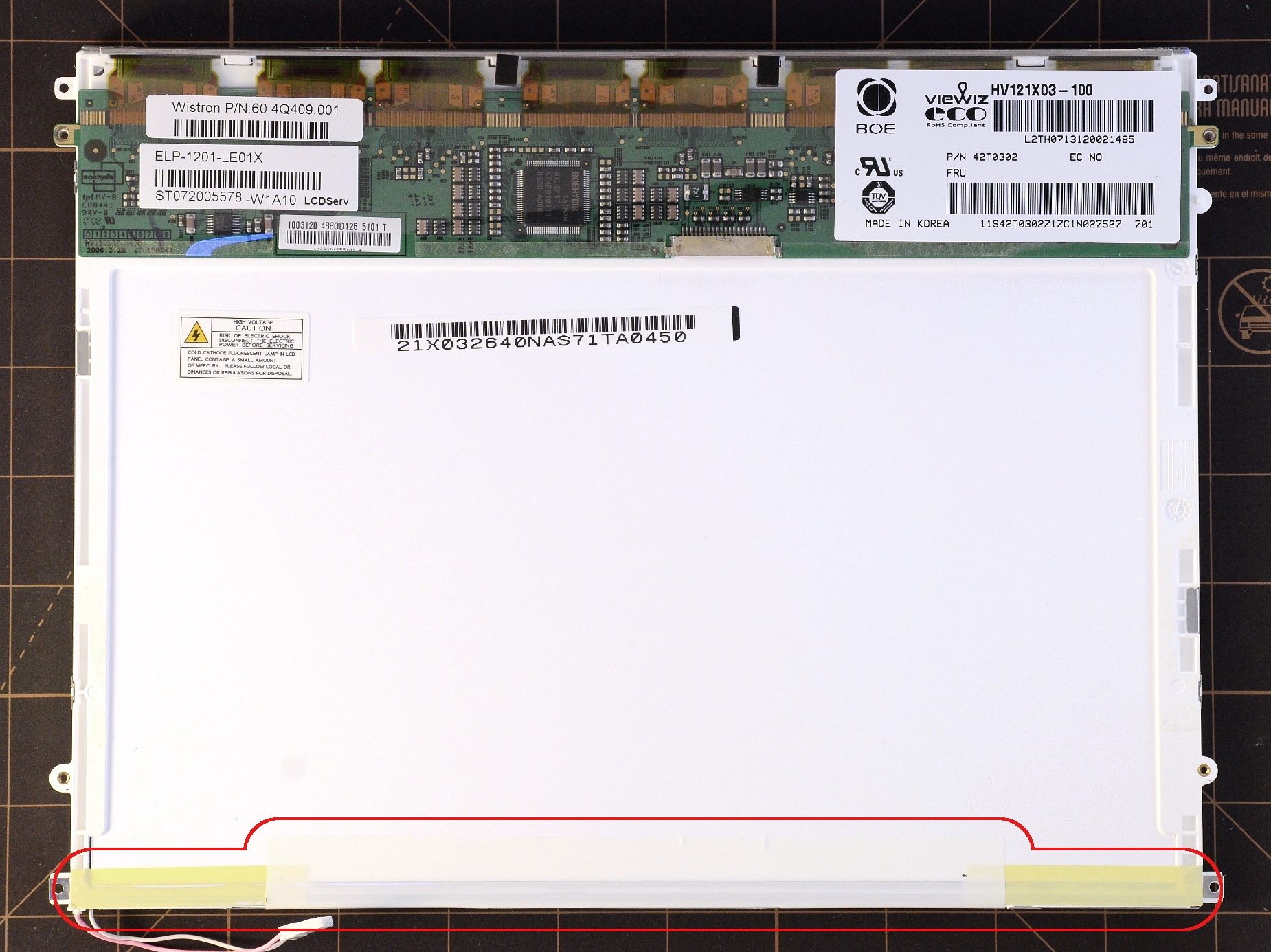
Above: The pieces of white and yellow tape removed in step 6 are circled in red.
The next few steps are optional to prevent any accidental short circuits between the LED supply and a grounded backlight bracket. A short to ground will blow either the fuse on the inverter board (there's only one), or fuse F2 on the top of the motherboard between the LCD cable connector and the processor socket.
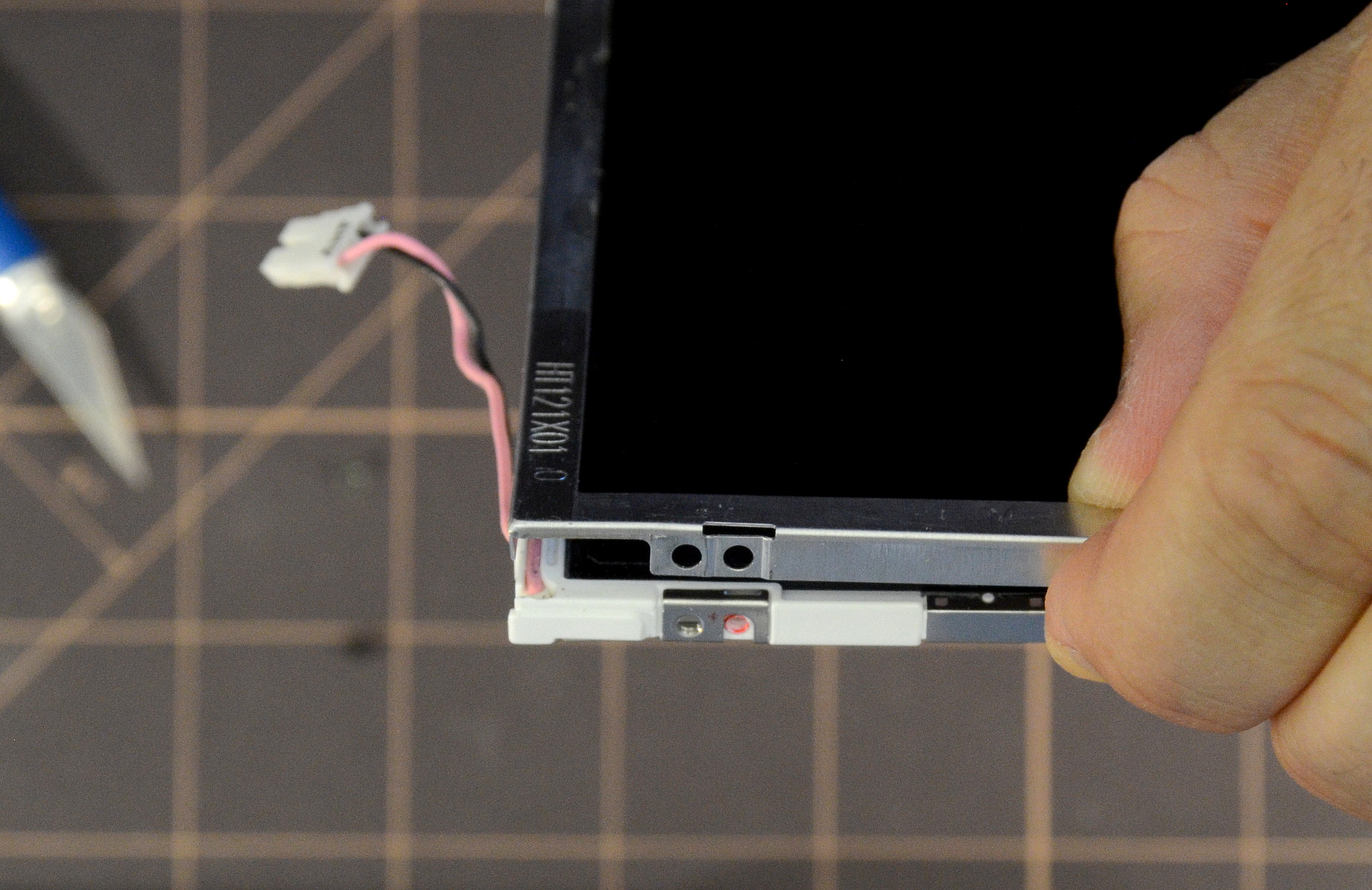
Remove the metal clips on the sides of the panel that cover the plastic mounting tabs and are secured to the white plastic frame with tiny screws. After removing the clips, replace the screws to re-secure the underlying metal tabs extending from the backlight bracket.
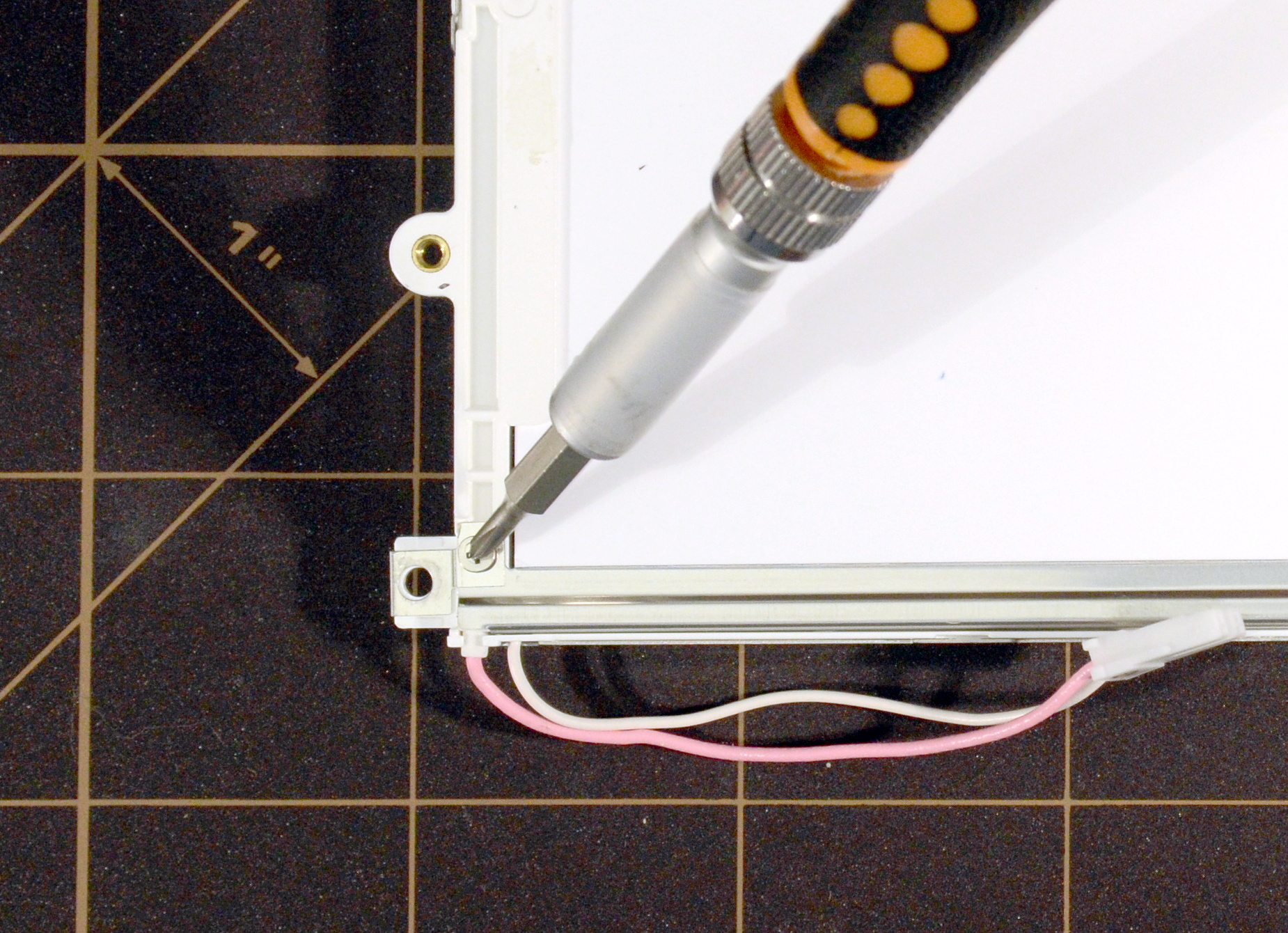

Above: Remove the backlight grounding clips by first unscrewing the screw fastening them to the backlight bracket, then sliding them off the plastic mounting tab.
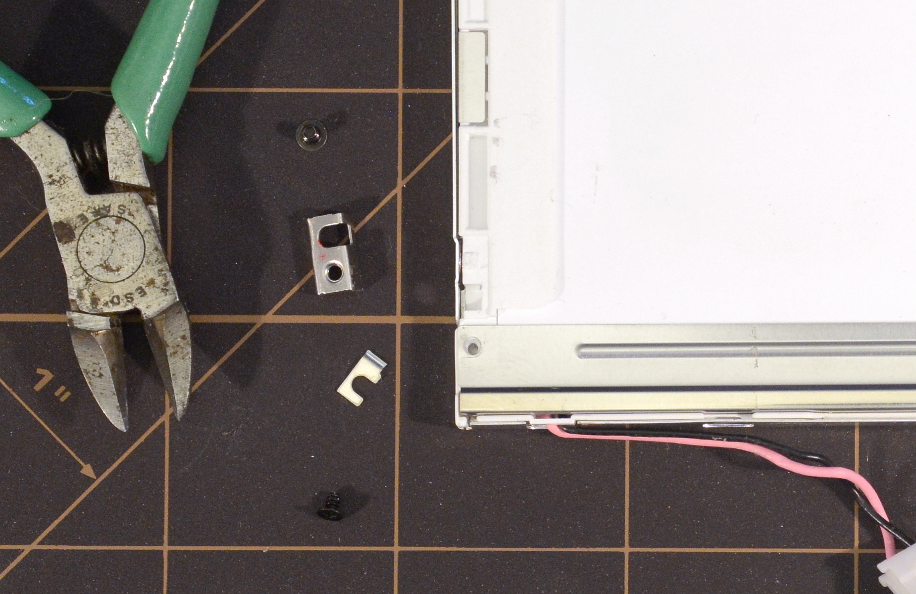
The metal clips removed in the previous step connect the backlight bracket to ground, but also function as reinforcements and thin spacers around the panel's plastic mounting tab. We'll need to put them back during reassembly for everything to fit perfectly, but we don't want them to connect the backlight bracket to ground. The solution: Cut the clip in half so that only the portion surrounding the white plastic mounting tab remains (see below). Don't replace the clips now; we'll put them back onto the mounting tabs later during final reassembly after finishing the LED installation.
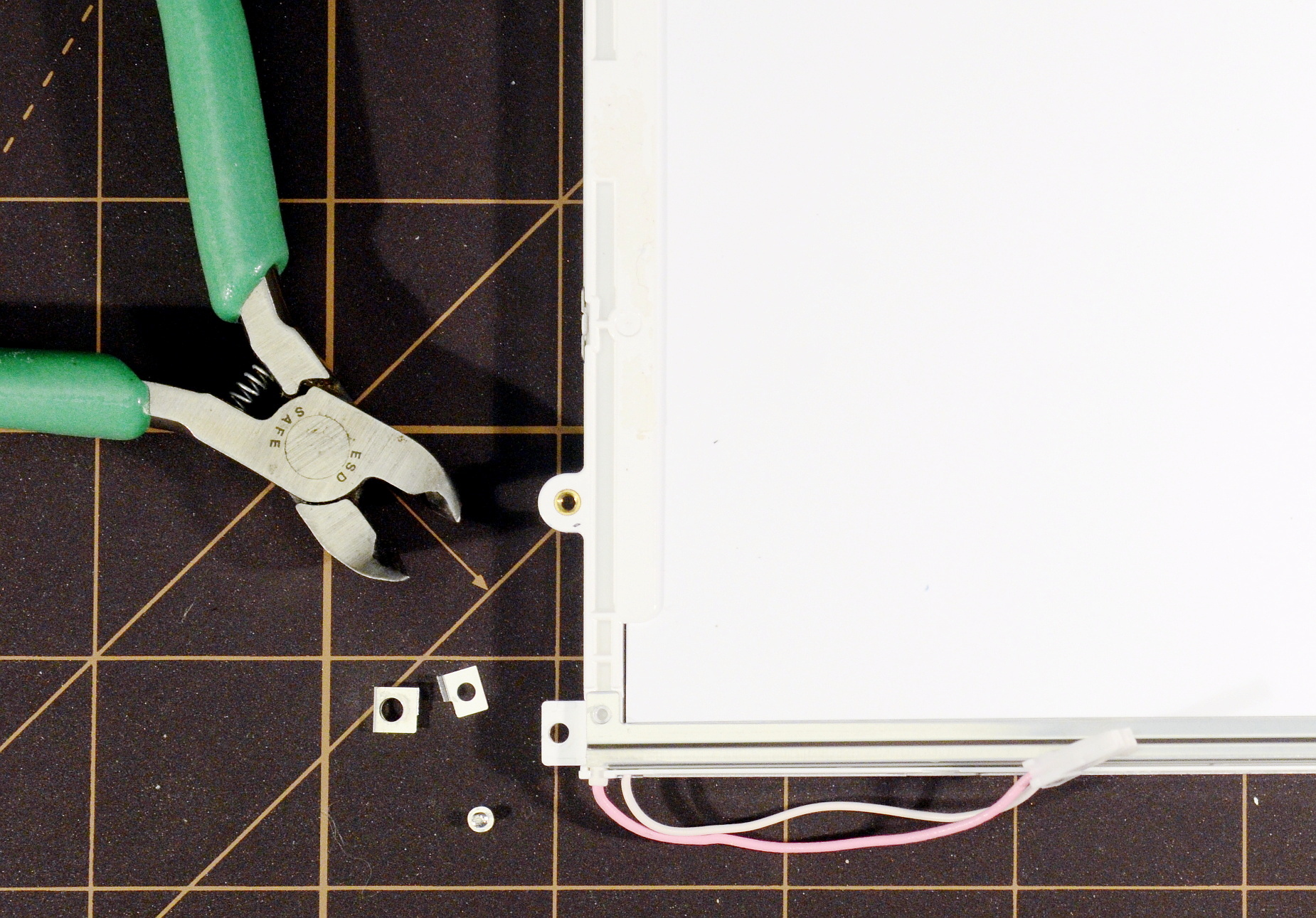
Above: The two clips on either side of the panel that connect the backlight bracket to ground also function as spacers and reinforcements around the plastic mounting tabs. We cut the connection to the backlight bracket off each clip, and will replace the clips back onto the mounting tabs later during final reassembly.
The next steps follow the same pattern as the other screens; skip down to CCFL Removal.
Remove any tape along the bottom of the panel that secures the metal front frame to the plastic inner frame, backlight bracket, and rear reflector.
Carefully remove (or just peel up the side of) the white protective tape along the right side of the panel. This tape covers three short, flexible ribbon cable tabs extending from the side of the glass LCD layer. The connections between the ribbon and glass are fragile; do not pull on the exposed tabs.
Unscrew the two black machine screws on the sides of the screen near the bottom that attach the metal outer frame to the inner plastic frame.

Above left: Remove the tape along the bottom and right side of the panel that secures the metal outer frame to the inner plastic frame, backlight bracket, and rear reflector. Also remove the two black screws, one on the left and one on the right (blue arrows), that attach the metal frame to the bottom of the plastic inner frame.
Above right: Panel after tape and screw removal. The protective white tape along the right of the screen covered three flexible cable tabs that curl from the front of the screen and protrude slightly above the frame. Take care handling the tabs as their connection to the glass LCD layer is fragile.
Leave the flexible tabs along the right side of the panel exposed for now; be careful not to abuse them by tugging, yanking, or shocking them (flexing is fine, just touching them also won't break anything). Do not replace the black screws we removed from the sides of the frame, as we still need to pop the metal frame open later.
The next few steps are optional to prevent any accidental short circuits between the LED supply and a grounded backlight bracket. A short to ground will blow either the fuse on the inverter board (there's only one), or fuse F2 on the top of the motherboard between the LCD cable connector and the processor socket.
Remove the two tiny black screws on the back of the panel that connect the backlight bracket to the two metal side-mounting clips (one on each side).
The side-mounting clips both provide the mounting threads for the hinges and connect the backlight bracket to ground. To sever the ground path, we cut off the tab that connects to the backlight bracket. The connecting tabs can simply be bent back and cut with diagonals, though this will probably leave a raised sharp edge.
Personally, I prefer to remove the clips, make a clean cut cut, and replace. The clips wrap around the plastic inner frame, so it's necessary to pop open a few of the hasps holding the outer metal and inner plastic frames together, separate the halves by a few millimeters, pull each clip free, cut it, return it to the plastic frame, then close the metal frame back into position.
Return the two small screws that fasten the backlight bracket to the plastic frame.
Above left: Release and lift the metal outer frame from the panel by a few millimeters in order to slide the mounting/grounding clip out of the panel. Removing the clip allows for a cleaner cut.
Above right: Picture of the removed mounting clip after cutting off the tab that provides a ground path for the metal backlight bracket. The black screw at top fastened the metal frame to the mounting clip. The black screw at bottom fastened the clip to the backlight bracket and the backlight bracket to the plastic inner frame.
Samsung screens are dead easy to prepare for LED installation.
Remove the white and the yellow pieces of polyester tape along the bottom and sides of the panel that secure the frame, backlight bracket, and rear reflector surface to one another. Don't mess with the tape along the top of the screen.
Remove the aluminum tape on the bottom right that provides an electrical ground connection between the backlight bracket and outer metal frame.

Above: Remove tape that secures the metal outer frame to the plastic inner frame, backlight bracket, and rear reflector from along the bottom and sides of the panel. The Samsung backlight bracket is grounded to the frame by a piece of conductive aluminum tape (circled in red). Remove this tape to break the ground connection.
...and with that the Samsung screens are ready for CCFL removal.
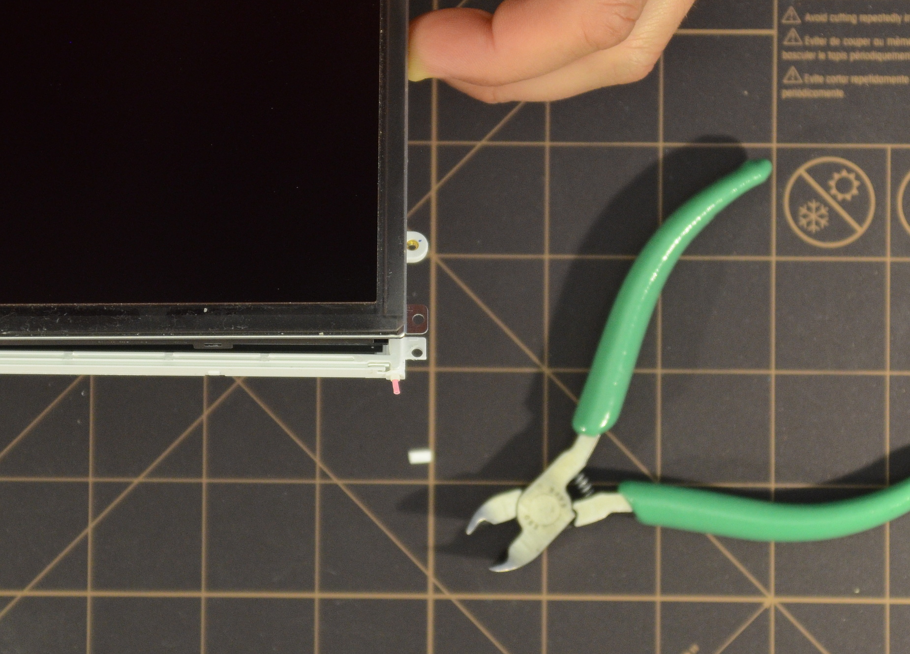
The easiest way to remove the original CCFL is to snip the wires free at both ends of the tube, trim away the thin plastic tabs holding the backlight tube in place at both ends, and then carefully pull the CCFL tube out of the panel. We need to momentarily separate the metal outer frame from the panel by a few millimeters, but there's no other panel disassembly required. This removal strategy also clears the way for easy, slide-in LED installation.
Gently pop apart the snap-together hasps along the front of the panel and one or two along each side using a small flat-blade screwdriver. Raise the metal outer frame up and away from the inner white plastic frame by a few millimeters, just enough to expose the backlight wires.
Unthread the backlight wires from the inner white plastic frame and pull them forward out from the panel. On some panels (usually AFFS), the pink wire is already routed straight forward out of the frame.
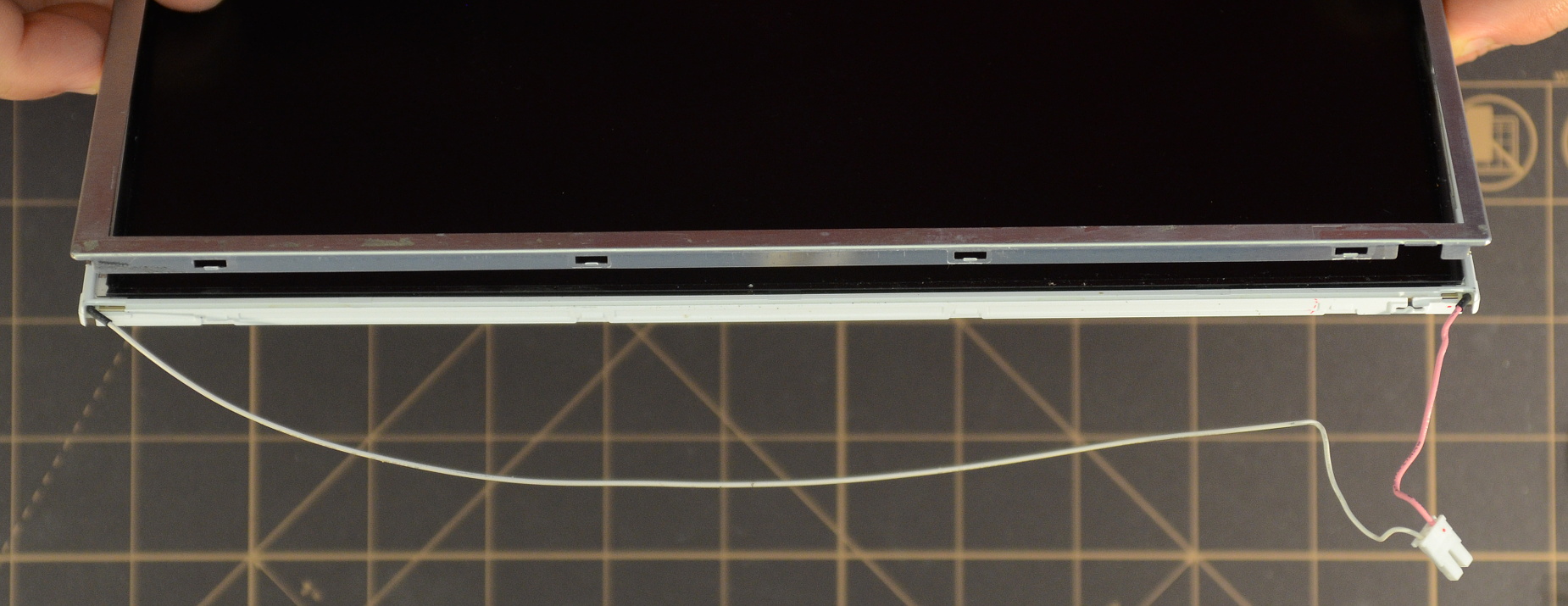
Above: LCD panel after pulling open the metal outer frame and unthreading the backlight wires from the inner plastic frame.
Cut the left wire (white/black) as flush to the top of the plastic inner frame as possible.
Cut the right wire (pink/red) to leave a little bit of wire in place that we can get a grip on with needle-nose pliers later.

Above: LCD panel after cutting backlight wires to allow easier extraction.
AFFS/Tablet screens only: The lower mounting tabs on the tablet (AFFS) screens will partially obstruct access to the backlight channel in later steps. Trim the right tab by cutting off the plastic just below the mounting hole.
Above: Closeup of the right mounting tab on a tablet LCD panel trimmed to remove the portion of the tab that obstructs clear access to the backlight channel.
Snap the metal frame back into place. Make sure all hasps along the bottom and both sides are mated.
The CCFL backlight tube sits in a channel formed by the backlight reflector bracket. The channel runs across the bottom of the screen, and is partly or completely covered on both sides by thin plastic that's part of the white inner plastic frame. Clip away this plastic to expose the white silicone rubber boots that cap both ends of the CCFL tube. Note that the silicone boots start out mostly exposed on some AFFS screens; it's probably only necessary to clip away plastic on the right (pink-wire) side.

Above: The backlight channel in the LCD panel is covered by thin pieces of inner white plastic frame. Cutting away this plastic exposes the backlight channel and the silicone boots that cap both ends of the CCFL tube.
Using small needle-nose pliers, carefully pull the left-hand (black/white wire side) silicone boot out of the panel. Extract only the boot; leave the wire and tube behind. Don't worry if the boot tears or it's necessary to extract it as multiple pieces. If the boot tears and pieces are left inside, poke them out later after removing the CCFL tube.
Again using small needle nose pliers, grasp the remaining stub of the pink/red wire on the right-hand side of the panel and gently slide the tube out. The tube will offer slight resistance due to one or more clear silicone o-rings that brace it within the channel. Pull gently and slowly.

Above: Remove one silicone boot from the left side of the CCFL tube, then slowly pull the tube and the other boot out from the right side using needle-nose pliers.
After removing the CCFL tube, inspect the openings on both sides of the now empty backlight bracket. Use a hobby knife (e.g., X-acto) to trim any remaining plastic away from the opening such that there's unobstructed access to the backlight channel.

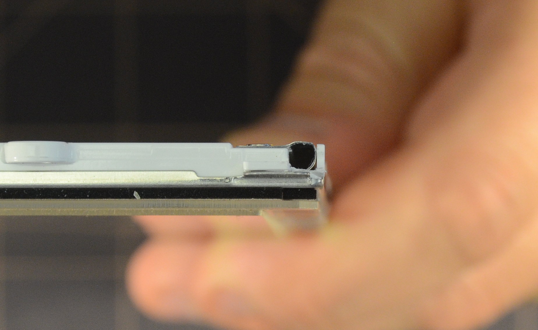
Above left: Closeup of the empty backlight channel of TN panel LTN121XJ-L07. The TN panels have square-shaped backlight channels. The small 'shelf' protruding into the inside of the backlight channel is the rear white reflector sheet.
Above right: Closeup of the empty backlight channel of AFFS panel HV121X03-100. The AFFS panels have backlight channels with more rounded-off corners. Again, the rear reflector sheet protrudes into the channel.
Panel HT121X03-101 and similar only: Return the black screws that secure the sides of the metal front frame to the internal plastic frame.
Panel HT121X03-101 and similar only: Cut small pieces of paper to cover the flexible cable tabs along the side of the panel and prevent replacement tape (next step) from sticking to the tabs.
Replace any tape removed during panel disassembly. The original tape is likely not reusable; clear polyester packing tape makes an excellent replacement.

Above: Panel HT121X03-101 reassembled with paper pieces (step 12) covering the flexible cable tabs and transparent polyester packing tape replacing the tape removed from the right side during disassembly. In this picture, the tape along the bottom of the panel hasn't yet been replaced.
Tablet panels only: replace the Wacom backplane.
At this point the panel should be completely reassembled (with the exception of the mounting tab clips on the tablet panels; those must be replaced after fitting the LED backlight).
If you don't want to fiddle around with extracting every last fraction of a percent of light out of the LED conversion, here's a simple fitting process with reliable results.
Note: The thin layer of Teflon on Daylight LED strips is intended to be left in place for installation.
 The majority of screens
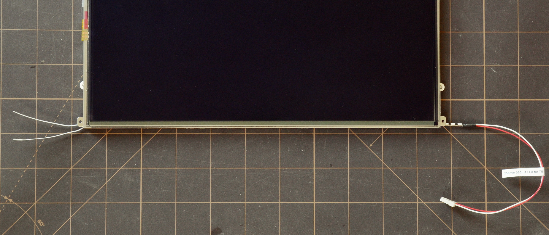
We want the LED strip positioned with the PCB straight up-and-down, and the LEDs pressed up against the screen's internal acrylic waveguide.
Slide a thin (10mil, .25mm) plastic shim into the metal backlight channel from the right side, the same side from which the CCFL wires extended. Then slide the LED strip into place in front of the shim, also from the right side. When sliding the LED strip into place, the fit should be just a bit snug. If the fit is loose, repeat the process adding another shim behind the strip. If the fit is too snug or the LED strip will not slide into place at all, remove a shim.
Due to a slight constriction at the entrance to the backlight channels of some screens, the best fit may be achieved with the shim sitting slightly inside the panel from the entrance side, and the entirely of the excess extending from the exit side.
Once you've found the desired fit, trim the excess shim material and you're done.
Most SXGA panels (and several other high-PPI panels, like the legendary R51 QXGA) will show a rippling LED pattern along the bottom of the screen if the LEDs are pressed right against the waveguide as above. If you have one of these screens and it does not show a pattern, you're a lucky bastard and I want to know more about it :-)

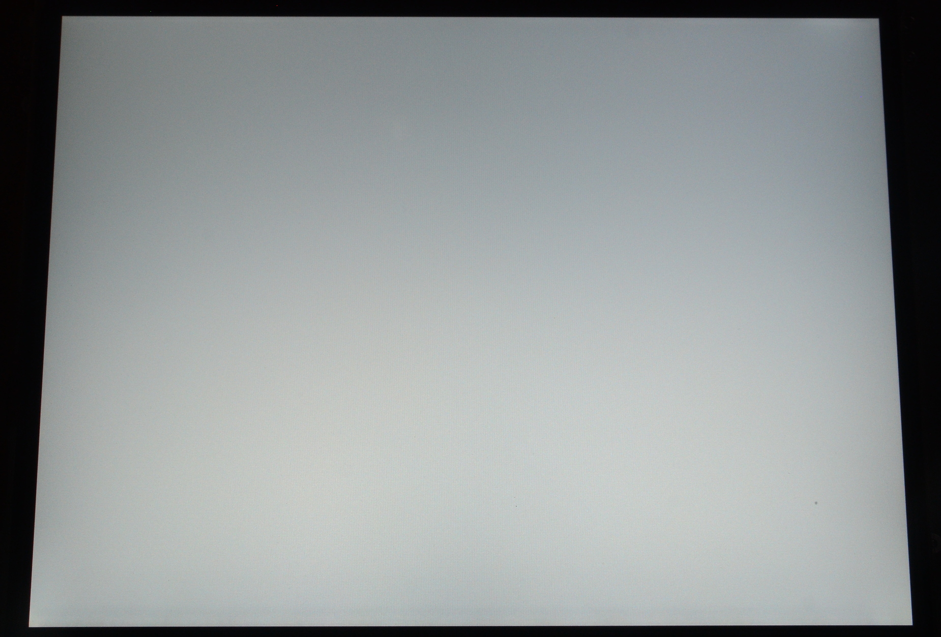
Left: 12.1" SXGA screens usually show a rippling pattern along the bottom of the screen with most LED strips.
Right: A Daylight strip used with a front accordian shim avoids the vast majority of the pattern.

In any case, the screens that do show LED 'rippling' need to be fitted differently.
Like before, we want the LED strip positioned with the PCB straight up-and-down, but with a small air space between the waveguide and LED strip. Instead of shimming the LED strip from behind, insert an accordian shim in front of the LED strip. The accordian strips are exactly the right length (once installed and flattened out slightly), so the easiest strategy is often to carefully feed it in along with the strip.
Once inserted, verify the strip is situated vertically. Fitting is complete.
The LED backlight strip slides into the empty backlight channel from the right side, the same side from which the CCFL wires extended. Nearly all of the strips that come in kits are 'universal' which means they're purposely too small to fit securely as-is. We'll need to shim them so that they're situated properly. If the LED strip rotates in the channel or sits too far back, the apparent screen illumination will dim and shift toward yellow.
Several of the Chinese kits provide double-sided adhesive tape and incomplete instructions suggesting the LEDs should be affixed firmly to the back or bottom of the backlight reflector bracket that held the CCFL. Don't do it. It sacrifices easily half the available brightness of the LEDs. It places them too far away from the waveguide and in the wrong position. Unlike the CCFL we're replacing, we want the LEDs to inject as much light as possible directly into the waveguide, not rely on reflection.
Bonding the LEDs with tape is also a complex task that requires completely disassembling the panel to extract the backlight bracket, and then once the LED strip is installed, it can't be removed. LEDs last longer than CCFLs, but they're not immortal. I consider easy slide-out, slide-in replacement a virtue worth preserving.
Most kits, including mine, come with strips that use top-emitting LEDs, that is, LEDs that shine directly out the top. We want to install these strips with the circuit board situated perfectly vertically and, except on SXGA screens, the LEDs pressed right against the internal acrylic waveguide.
A few kits (e.g., some of the xCCFL kits) come with side-emitting LEDs. These can't be mounted with the LEDs directly against the waveguide as they're usually set in the middle of the PCB strip. We still want to mount them as close to the waveguide as possible, and since the emission pattern of the side-emitting LEDs is actually angled upwards (not directly to the side), with the LEDs rotated to face downward slightly.
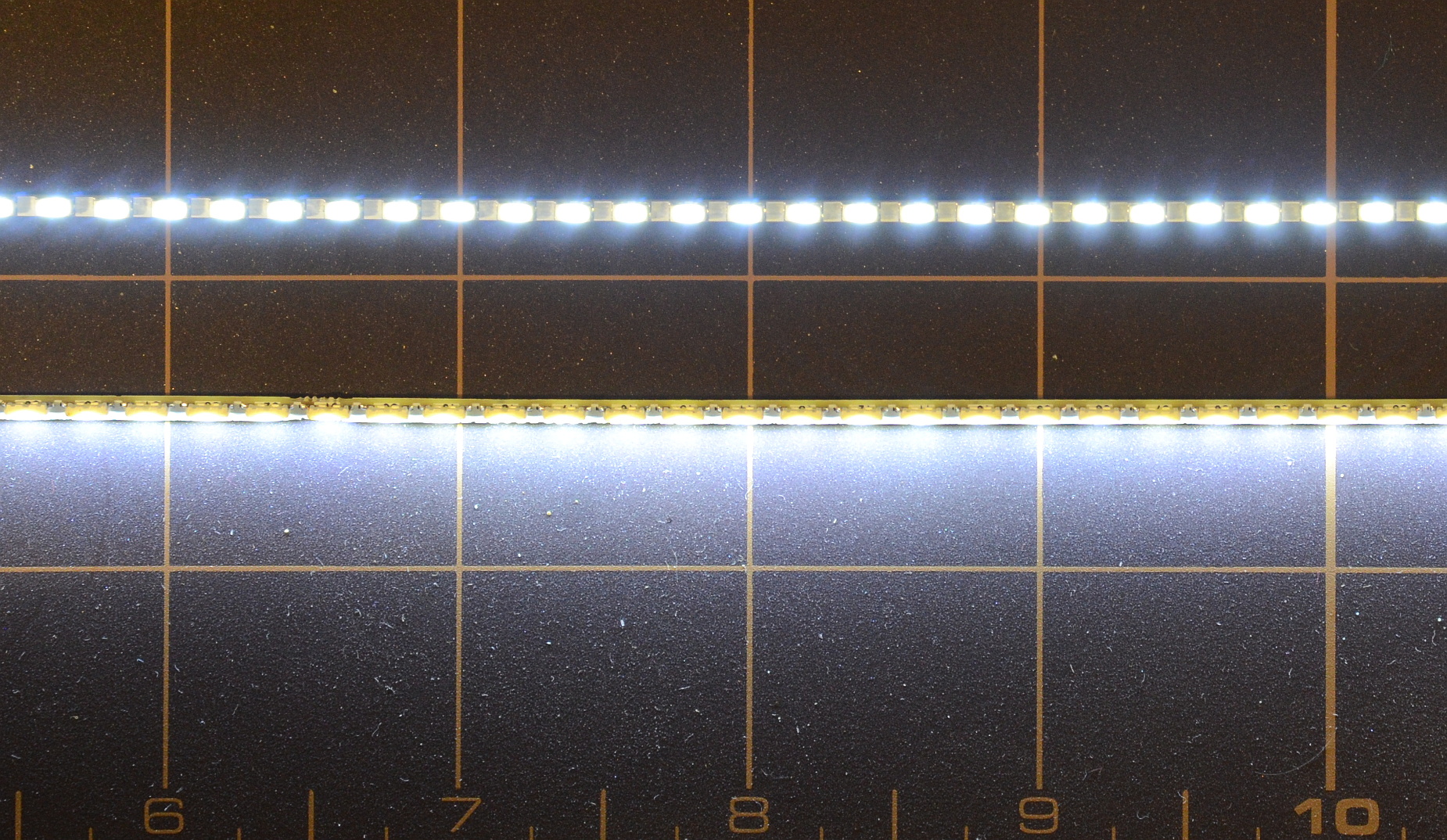
Above: Top-emitting LEDs (upper strip) shine straight up. Side-emitting LEDs (lower strip) emit [mostly] to the side. The strongest lobe of the emission pattern is actually pointed up slightly.
Thin plastic shims are the easiest way to keep strips with top-emitting LEDs in the proper position. We only need to fill 10-40 mils of space, and small plastic sheets with tight thickness tolerances are readily available from hobby supply stores in .005" through .05" thicknesses. I personally use PTFE (Teflon) sheet, as this guarantees tight fits will still slide into place easily with no binding. However, the cheaper and easier to find clear polyester sheets will also work well. Avoid ABS and polystyrene; they will soften as the LEDs get hot.
Although I personally no longer bother, you can adhere the shims to the LED strip if you want to. Polyester and teflon sheet are both available with adhesive backings, or make adhesive shims by applying a layer of adhesive transfer tape (e.g., Killer Red, which will adhere nicely even to PTFE) to the plastic sheet, then cutting the strip on a rotary-blade paper cutter. A straight-edge and hobby knife should also work nicely given sufficient care.
Above: A (trusty, rusty) rotary-blade paper cutter does precision work slicing thin strips off a plastic sheet. The red stripe across the top of the Teflon in the picture above is a strip of Killer Red tape for making the resulting shims adhesive.
The specific shim dimensions need to be determined by measurement (or trial and error) for each type of strip and screen. Don't forget to account for the shape of the specific backlight bracket, rounded off inner corners, the narrowing in the front of the backlight bracket where it clamps to the waveguide, and any protrusions into the channel, such as the rear reflector sheet.
That said, the shim behind the LED strip is typically on the order of 80 mils (2mm) high and 20 mils (.5mm) thick. A thin strip along the top and/or bottom isn't really necessary, but it can help secure against rotation.
Above: Close-up of a shimmed LED strip sliding into a Samsung TN panel. The necessary shims will be different for each screen and each kit, but this particular strip has two adhesive 10 mil strips (2mm high, .5mm thick) fixed to the back of the strip, and a narrow 10 mil strip (.25mm thick) along the top and bottom. The strip is a good fit that will not shift or rotate out of position.
The LED strips can also be shimmed into perfect position with a self-curing modeling putty like Sugru. This is also the only good option for holding side-emitting LED strips in the proper slightly down-rotated position.
Apply a generous blop of Sugru that's about three LEDs wide at 4-6 positions along the back of the LED strip. Knead each bead to wrap around the top and bottom being careful not to obscure the LED emitters.
Wait for the Sugru to cure.
Carve each bead into the approximate shape of the backlight channel using a hobby (X-acto) knife. Pay most careful attention to the flat sides along the top, back, and bottom. Taper the beads on both sides to ease entry and removal.
It's best to be conservative, remove small slivers, check the fit one bead at a time, adjust, repeat. Worst case, you remove too much and have to add more Sugru.
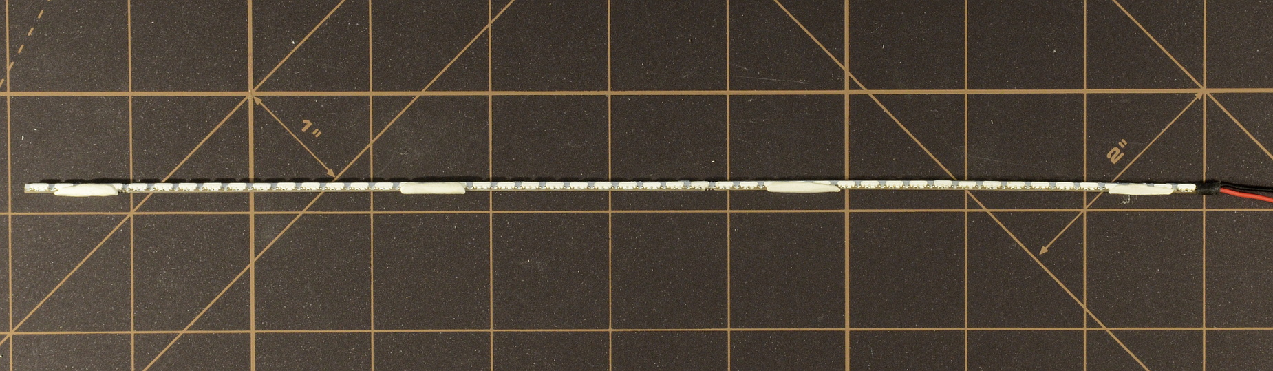
Above: Close-up of an xCCFL side-emitting LED strip shimmed with beads of carved Sugru. Sugru remains pliable with a bit of give after curing, so perfect precision isn't required for a good fit.
The Sugru strategy may require some practice, but the end results are as good as shimming with plastic strips. Like Teflon, Sugru is inherently non-stick after cure and slides into place easily without binding. It's also good for plugging both sides of the backlight channel after assembly to prevent light leakage from the sides of the channel.
SXGA and other high-PPI screens naturally pass less light through the glass matrix. These screens use a different waveguide and prism design that attempts to be more efficient by building one of the directional prism layers directly into the waveguide. This works very well for CCFL tubes, which give uniform light across their entire length. It's a serious complication when using individual LEDs.
Packing wide-angle, low-profile LEDs as close together as possible (which the Daylight strip does) helps a great deal. Placing a small gap between the LEDs and the internal waveguide will, along with everything else, take care of the rest of the problem. Experimentation indicates the gap has to be air; using a plastic spacer doesn't work.
This is where the accordian strip comes in. Placed in front of the LED strip, it adds an air gap by holding the LED strip away from the waveguide, but also holds the LED strip firmly in place against the backlight bracket. Shims can still be added behind the LED strip to adjust the size of the gap.
There's not much to final assembly as the shimming process has already fitted the LED strip into the panel. Some black electrical tape or a small plug of Sugru to cover the exposed openings on the backlight channel are a good idea but hardly necessary. On the tablet screens, don't forget to return the metal clips to the panel's lower tabs before mounting back into the lid.
The LED strip plugs into the modified LED driver/inverter, and the inverter plugs into the LCD cable. Note that the connector between the LCD cable and inverter isn't keyed in any way. On most models, it's nearly impossible to connect backward, but it's easier to connect the wrong way on X60 and X61 tablets. If you do connect it upside-down/backward, you'll blow fuse F2 on the motherboard. Consult the image below for correct orientation.
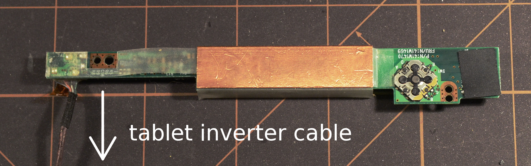
Above: It's possible to connect X60 and X61 tablet inverters to the LCD cable backward; doing so will blow fuse F2 on the motherboard. The image above shows the correct orientation of the cable. The inverter is shown in mounting position.
Lastly, connect the screen to the LCD cable as well and test everything out. Reassemble the lid and enjoy the new backlight.
Above: Front and rear hacker's-eye view of a kit and LED strip installed on an X61 with a Samsung TN panel. The panel's been mounted back onto the hinge rails, but the rear lid cover and front bezel have not yet been returned to place.