
ThinkPad LED Driver #3
for the X60, X60s, X60t, X61t, X61s, and X61t in particular

 gEDA PCB source
 Gerber files
 BOM
BOM
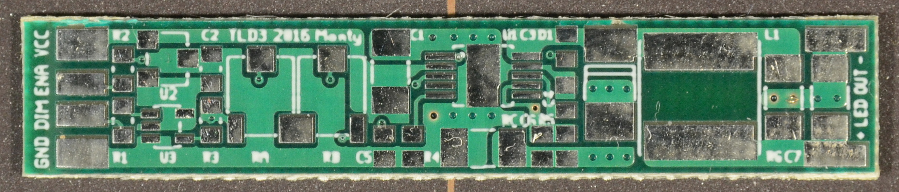
ThinkPad LED Driver #3 (TLD3) is a slight refinement of layout TLD1, replacing the brightness range trim and shaping resistors with two multiturn cermet potentiometers. They allow trimming a TLD3 board for any model without soldering.
Like TLD1, the TLD3 is a buck-topology LED driver based on the Texas Instruments TPS92510 controller IC. It provides a single channel of dimmable current-regulated output intended for 3S LED strings operating between 7V to 9.6V and a design output current of 600mA from an unregulated input of 10-24V.
As mentioned in the FAQ, CCFL ThinkPads all use the same brightness control system, but different ThinkPads use different brightness ranges and step spacing designed to work with specific CCFL lamps. LEDs behave differently, and the LED driver boards must be 'trimmed' for the best behavior with a given model's brightness range.
The TLD3 board includes two potentiometers that allow it to be trimmed for any model, or adjusted by the user to suit their own preferences.
Both potentiometers are multiturn cermets with a full adjustment range of 11 turns. When adjusted past either end of the range, the potentiometer wiper 'idles' and up to a full turn in the opposite direction is required before the wiper starts moving again.
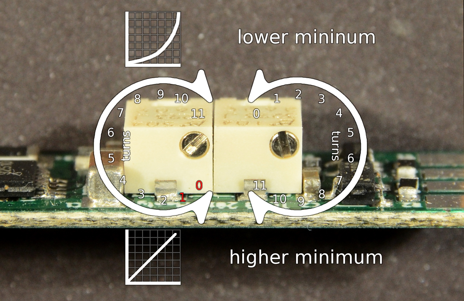
Above: Two potentiometers on the TLD3 adjust the shape of the brightness step spacing and the minimum brightness setting.
The left-hand potentiometer adjusts step spacing toward a more exponential step spacing in the clockwise direction, and toward a more linear spacing in the counter-clockwise direction. Linear spacing makes brighter steps feel closer together and dimmer steps feel farther apart. Exponential spacing does the opposite, making brighter steps feel farther apart and dimmer steps closer together.
Starting from a full-counterclockwise position, the first turn or so (once the adjustment starts moving) is not in the useful adjustment range. Until adjustment has reached the first full turn, low brightness steps will flicker slightly as the lowpass filter that converts the ThinkPad's PWM brightness signal to a smooth analog level is not yet fully functioning.
The right potentiometer adjusts TLD3's output at the ThinkPad's minimum brightness setting. Clockwise increases the minimum brightness output, and counter-clockwise decreases it. Note the the TLD3 has an inherent minimum output of about 7-10mA. Attemting to adjust below this level has no affect on the minimum brightness setting, and will also decrease the brightness level of steps above minimum.
This adjustment process restores a default X41 adjustment.
If an ammeter is available, place it inline with one leg or the other of the LED strip.
Rough adjustment is still possible if an ammeter is not available:
This adjustment process restores a default X60 adjustment.
Note: An X60, X60s or X60T machine using Coreboot or Libreboot behaves more like an X61 where backlight adjustment is concerned. Windows 10 will also set a n X61-like brightness stepping. The adjustment outlined here will work either way.
If an ammeter is available, place it inline with one leg or the other of the LED strip.
Rough adjustment is still possible if an ammeter is not available:
This adjustment process restores a default X61 adjustment.
If an ammeter is available, place it inline with one leg or the other of the LED strip.
Rough adjustment is still possible if an ammeter is not available:
In addition to the below, design requirements and notes from TLD1 still apply.
The adjustable range of TLD3 required revision of capacitance values in the PWM-to-analog lowpass, as well as co-opting the current sense decoupling capacitor C6 into being a more active part of the filter. This was to even out the time-constant behavior of the lowpass across the adjustment range such that the lowpass would smooth adequately without overly damping brightness changes.
For good measure, I also reduced current flow within the dimming circuit, as the current flows across both wipers of both potentiometers.
All passives on the TLD3 board are now oriented vertically in an attempt to reduce their exposure to board flex during installation and handling.
Although TLD3 runs at 350kHz, I was surprised to find in testing that several molded powdered-iron core inductors performed as well as the ferrite inductors I'd been using in TLD1 and TLD2. The inductors also had significantly higher current and saturation ratings, and were more physically robust.
TLD3 is a revision of the original TLD1 prototype taking into account several minor refinements. As of May 2016, TLD3 replaces the use of TLD1 and TLD2 in Daylight (600mA) kits for all Thinkpad models.