
ThinkPad LED Driver #2
for the X60, X60s, X60t, X61t, X61s, and X61t in particular

 gEDA PCB source
 Gerber files
 BOM (335mA)
BOM (600mA)
BOM (335mA)
BOM (600mA)
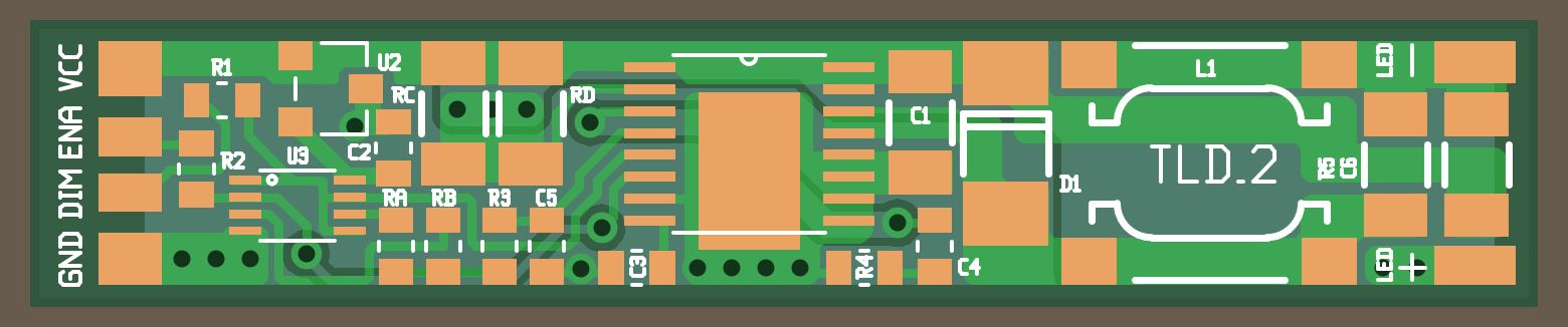
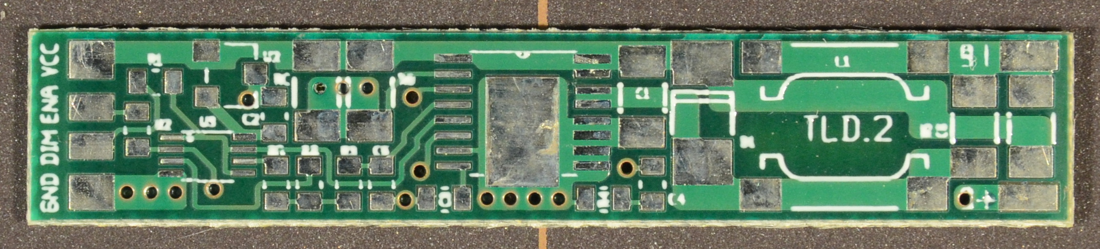
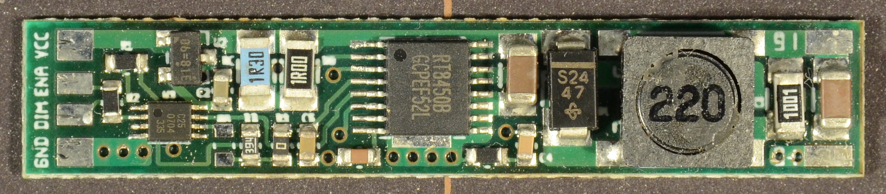
ThinkPad LED Driver #2 (TLD2) was an alternate prototype designed at the same time as TLD1. It is a buck-topology LED driver based on the Richtek 8450B controller IC. Like TLD1, it provides a single channel of dimmable current-regulated output intended for 3S LED strings operating between 7V to 9.6V and a design output current of up to 600mA from an unregulated input of 10-24V.
Design requirements are the same as for TLD1.
TLD2 was originally intended to hedge my bets on TLD1. It's a more complex circuit around a more complex controller that's slightly less efficient than TLD1 due to using a bipolar on-chip switch rather than a MOSFET.
The Richtek chip has built-in lowpass infrastructure intended to convert an input PWM waveform to an analog level for dimming. Translation is fairly linear.
The built-in conversion overshoots the top of the analog brightness range slightly in order to guarantee that a 100% duty cycle saturates to full brightness. As a result, the top two brightness levels are closer together than they should be otherwise. Minimum brightness is only about 1/6th the level of maximum brightness
U3, RA, RB, R3 and C5 form a supplemental brightness control circuit intended to modify the built-in linear conversion with an additional pullup and pulldown. In practice, the TLD2 was only used on X60 drivers, and only the pulldown is used (to reduce the minimum brightness level).
Unlike many driver chips, the various logic inputs are not rated to VCC; exceeding the maximum input listed on the datasheet will damage (but not entirely cripple) the chip. The resulting misbehvior looks a great deal like static discharge damage.
The RT8450B is also easily static damaged, though not as easily as the TPS92510. Static damage usually manifests as regulation metastability; output current unexpectedly fluctuates with changes in input voltage. The circuit still works, it just 'acts funny'.
Assembled circuits appear to be more normally robust against static, likely due to large external capacitances protecting the relevant sense inputs. As yet, I've not had an assembled board suffer static damage.
Due to the 'max brightness' overshoot noted above, TLD2 was only used in X60 drivers where the upper two brightness steps were so far apart it made little difference. 50 hand-soldered boards from the prototype run became the first generation of X60 LED kits (Original and Daylight). With the introduction of TLD3, remaining TLD2 boards will be used in 'Original' (335mA) X60 kits until the stock is depleted.